Wireless exercise signal receiver system with personal portable unit as relay transmitter
Inactive Publication Date: 2015-01-15
BION
View PDF10 Cites 13 Cited by
Summary
Abstract
Description
Claims
Application Information
AI Technical Summary
This helps you quickly interpret patents by identifying the three key elements:
Problems solved by technology
Method used
Benefits of technology
Benefits of technology
The present invention provides a wireless exercise signal receiver system with a personal portable unit as a relaytransmitter. This solves problems faced by current devices.
Problems solved by technology
And, a public field is often not free of charge and users have to spend money and time to achieve their purposes.
Although the conventional exercise system may detect all sorts of variations of heartbeat, such a design generally cannot satisfy the needs for multiple-purpose body fitting and exercise.
Method used
Image
Click on the blue label to locate the original text in one second.
Reading with bidirectional positioning of images and text.
Examples
first embodiment
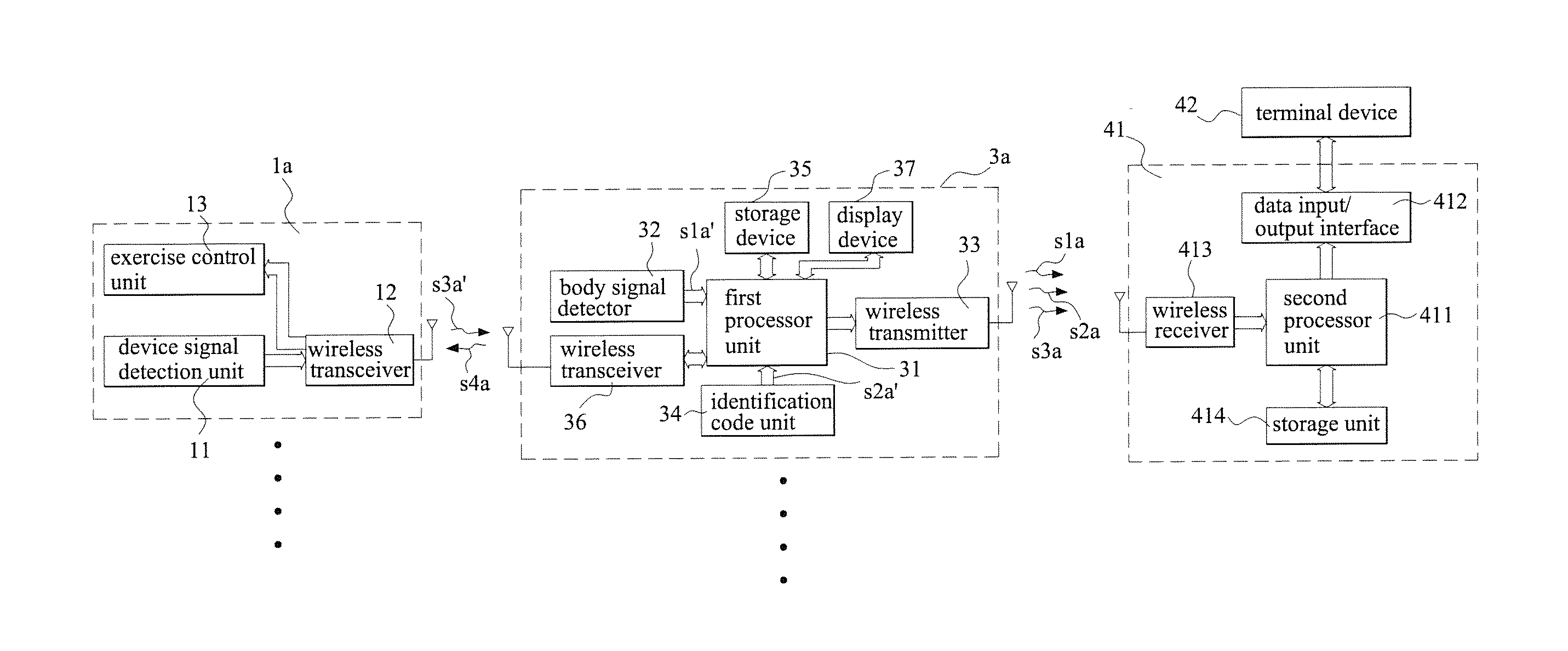
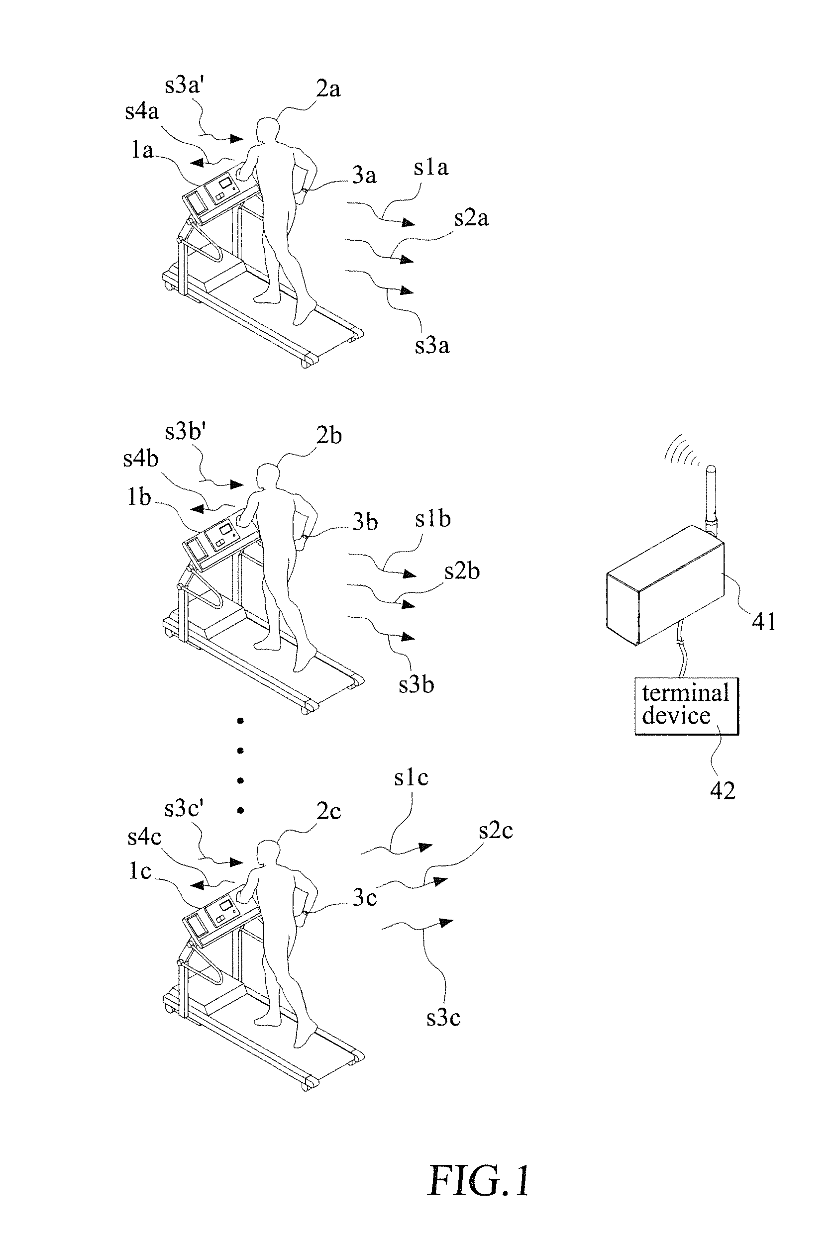
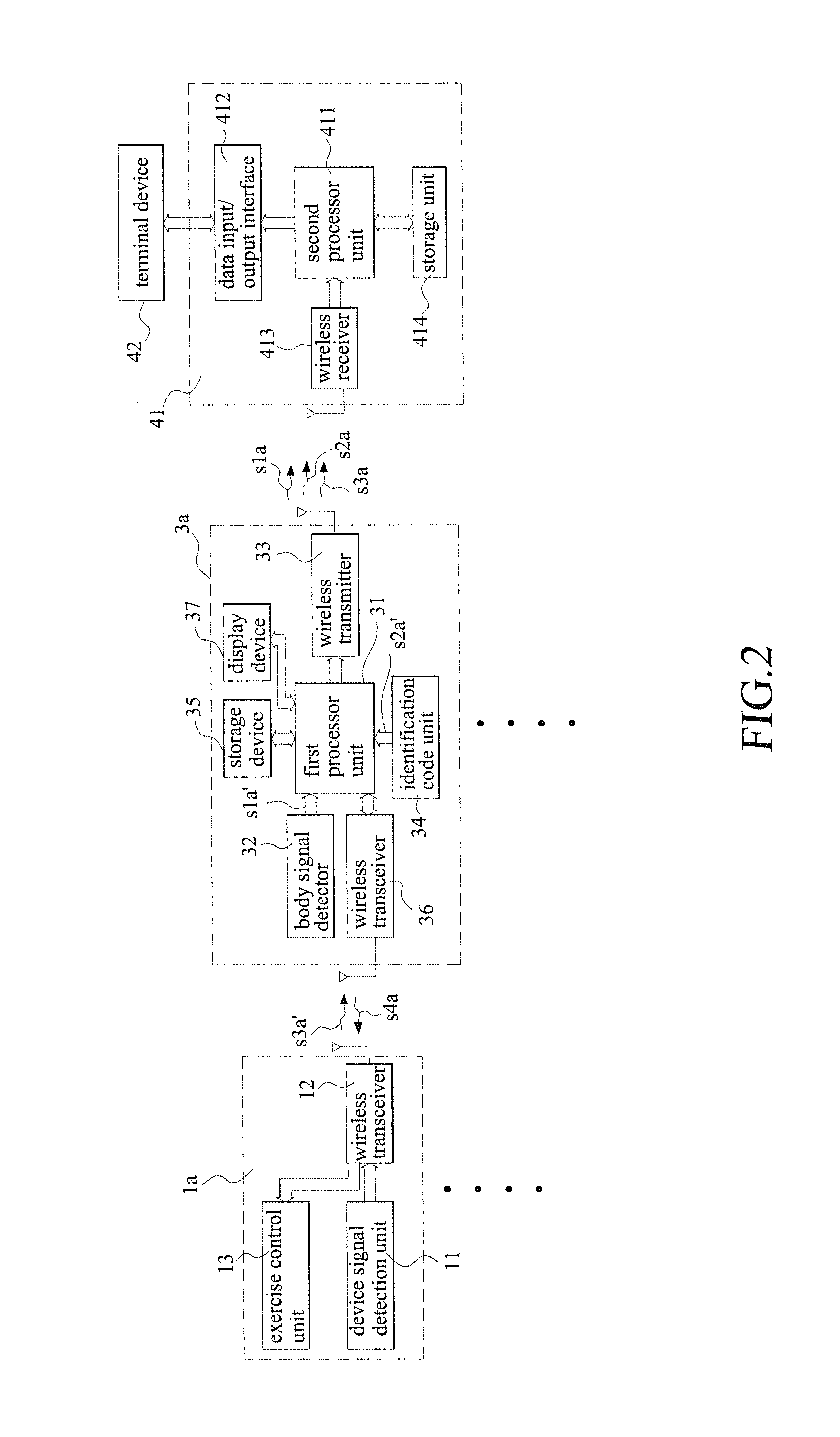
[0023]With reference to the drawings and in particular to FIG. 1, which is a schematic view showing the present invention, as shown in the drawing, an exercise signal receiver system with a personal portable unit as a relay transmitter according to the present invention comprises a plurality of exercise devices 1a, 1b, 1c. Each of the exercise devices 1a, 1b, 1c is provided for use by a user 2a, 2b, 2c. When the users 2a, 2b, 2c use the exercise devices 1a, 1b, 1c, each of the users 2a, 2b, 2c puts on a portable unit 3a, 3b, 3c to serve as a relay transmitter.
[0024]Each of the portable units 3a, 3b, 3c generates a wireless body signal s1a, s1b, s1c and a wireless identification code s2a, s2b, s2c that are transmitted in a wireless manner and is received by a common receiving station 41. The common receiving station 41 receives wireless body signal s1a, s1b, s1c and wireless identification codes s2a, s2b, s2c that are displayed on a terminal device 42 electrically connected to the co...
third embodiment
[0039]Referring to FIG. 4, which is a schematic view of the present invention, in the instant embodiment, the portable unit 6a, 6b, 6c is an on-waist counter type portable unit that is worn on the waist of a user to provide a counting function when the user is doing outdoor exercise or aerobic exercise. Each of the portable units 6a, 6b, 6c generates a wireless body signal s1a, s1b, s1c and a wireless identification code s2a, s2b, s2c that are transmitted to the common receiving station 41.
fourth embodiment
[0040]Referring to FIG. 5, which is a schematic view of the present invention, in the instant embodiment, a portable unit 7a, 7b, 7c is a speedometer of a bicycle rode by the user 2a, 2b, 2c in order to provide a speed detection function when the user is doing outdoor exercise or aerobic exercise. The portable unit 7a, 7b, 7c may also be configured as a detector for detecting the heartbeat of the user. Each of the portable units 7a, 7b, 7c generates a wireless body signal s1a, s1b, s1c , a wireless identification code s2a, s2b, s2c and a wireless device signal s3a, s3b, s3c that are transmitted to the common receiving station 41.
[0041]Referring to FIG. 6, which is a schematic view of a fifth embodiment of the present invention, in the instant embodiment, the components are identical to those of the embodiment shown in FIG. 3 and identical components are designated with the same reference numerals. FIG. 7 is a circuit system block diagram of the fifth embodiment of the present invent...
PUM
Abstract
Disclosed is an exercise signalreceiversystem with a personal portable unit as a relaytransmitter. Users, when using individual exercise devices, each put on a portable unit to transmit a wireless body signal and a wireless identification code of each user to a common receiving station. The common receiving station receives the identification code of each portable unit and a body signal corresponding to the identification code. The portable units also receive device signals and transmit the device signals to the common receiving station. The common receiving station is connectable via a data input / output interface to a terminal device.
Description
BACKGROUND OF THE INVENTION[0001]1. Field of the Invention[0002]The present invention relates to a wireless exercise signal receiversystem with a personal portable unit as a relaytransmitter, and in particular to a long-distance, multifunctional wireless centrally-receiving integrated system.[0003]2. The Related Arts[0004]The rise of living quality of modern people allows people of the developed countries and the developing countries to have more leisure time for doing exercise for body training and entertainment. In the condition of heavy population, it is very luxurious to have a field of a great area for exercise. And, a public field is often not free of charge and users have to spend money and time to achieve their purposes. Thus, a lot of indoor exercise devices have been develop and are available.[0005]The indoor exercise equipment that is available in the market is often provided with an exercise system that detects and transmits the heartbeat or a specific signal of the us...
Claims
Application Information
Patent Timeline
Application Date:The date an application was filed.
Publication Date:The date a patent or application was officially published.
First Publication Date:The earliest publication date of a patent with the same application number.
Issue Date:Publication date of the patent grant document.
PCT Entry Date:The Entry date of PCT National Phase.
Estimated Expiry Date:The statutory expiry date of a patent right according to the Patent Law, and it is the longest term of protection that the patent right can achieve without the termination of the patent right due to other reasons(Term extension factor has been taken into account ).
Invalid Date:Actual expiry date is based on effective date or publication date of legal transaction data of invalid patent.

