System and method for assessing cumulative effects of a failure

a technology of cumulative effects and system failures, applied in the direction of process and machine control, testing/monitoring control systems, instruments, etc., can solve the problems of reduced safety margin, lost or degraded function/performance, and no longer practicable analysis methods in terms of breadth of coverage and labor costs involved, so as to facilitate identification and evaluation, the effect of facilitating the review of analysis results

Active Publication Date: 2015-01-15
THE BOEING CO
View PDF1 Cites 27 Cited by
  • Summary
  • Abstract
  • Description
  • Claims
  • Application Information

AI Technical Summary

Benefits of technology

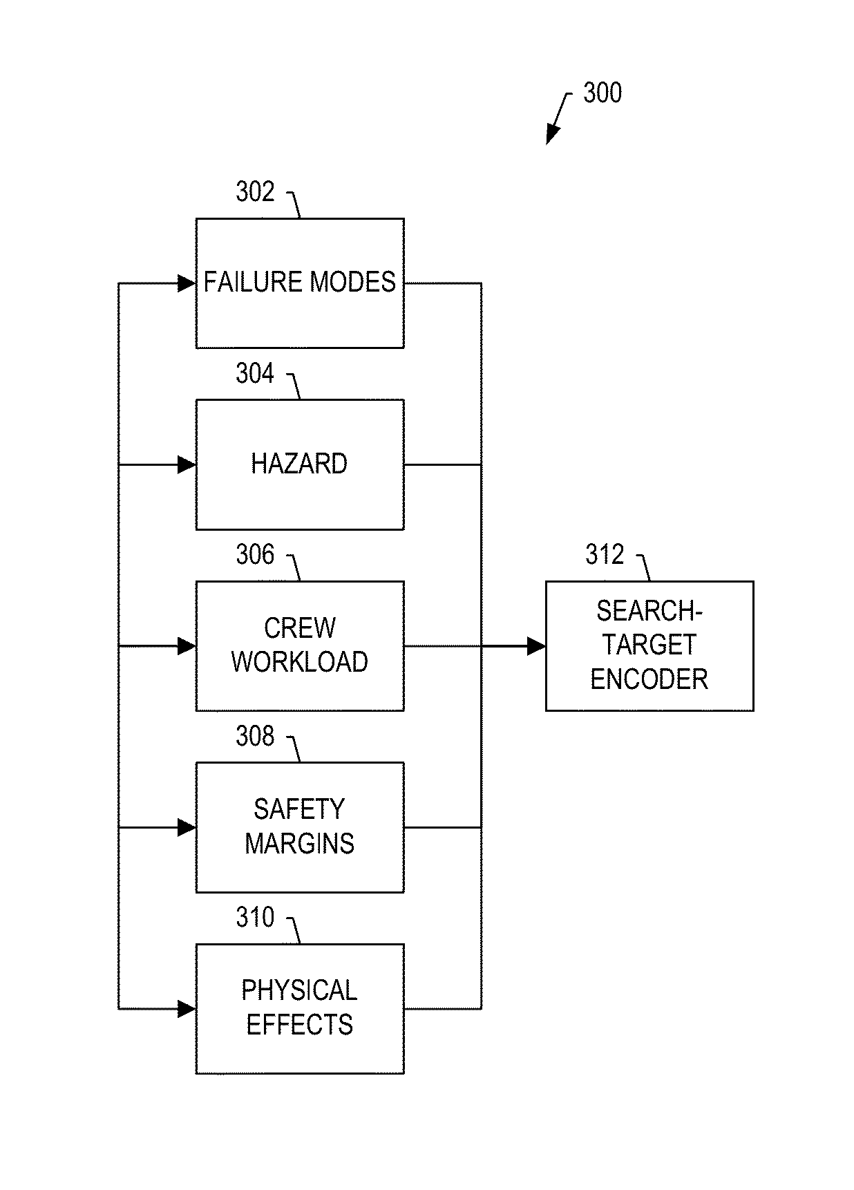
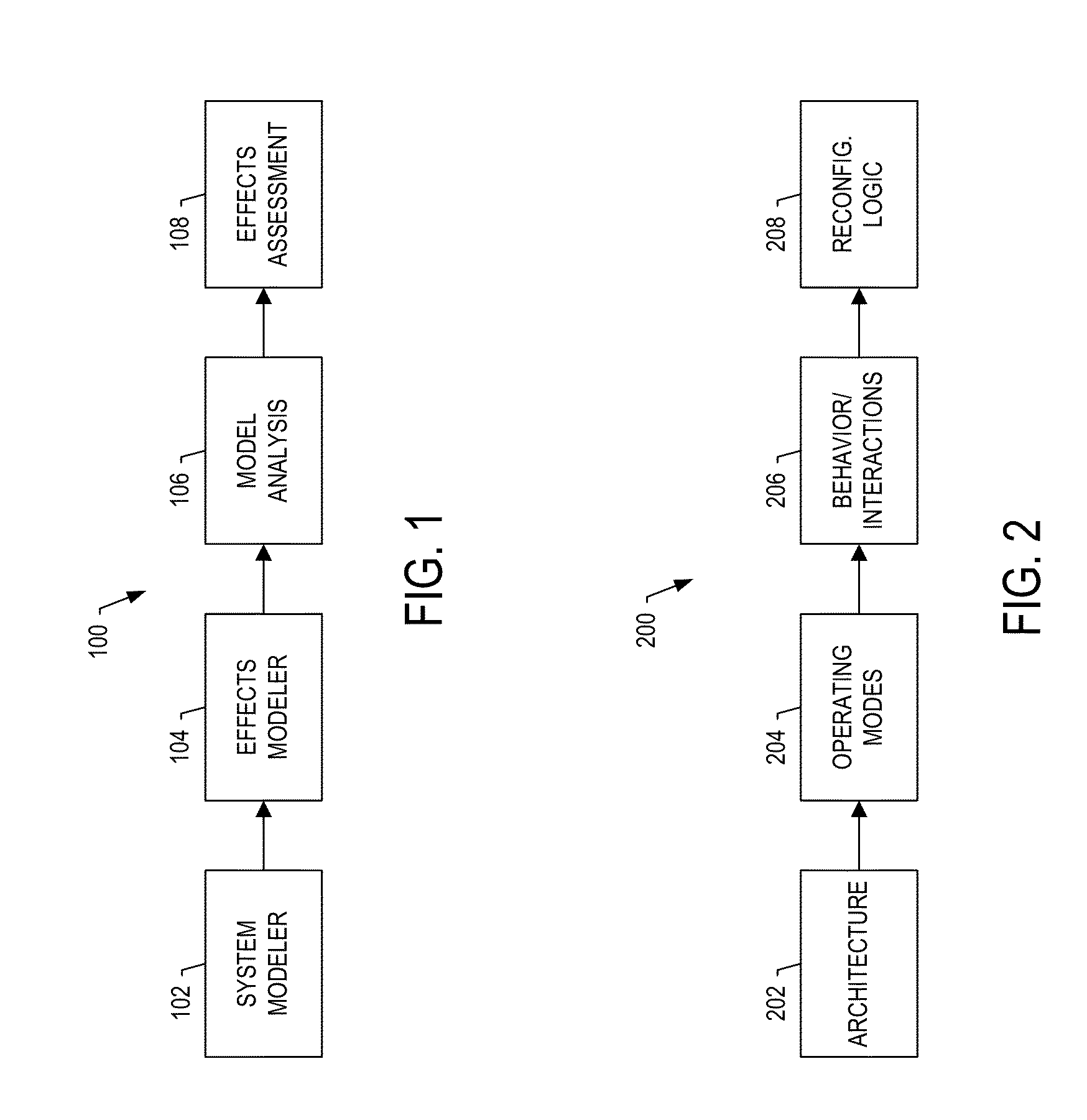
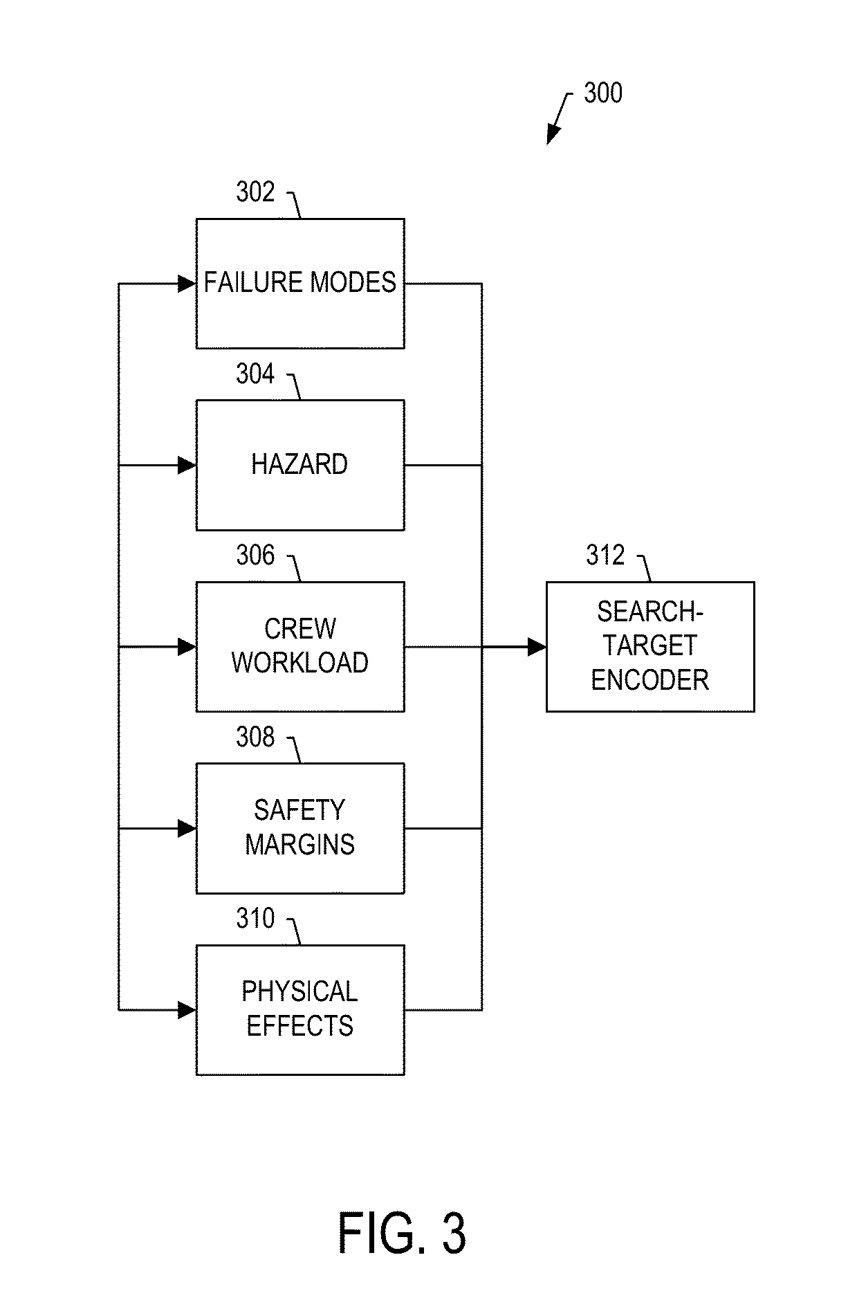
[0007]Example implementations of the present disclosure are generally directed to an improved system for assessing cumulative effects of system failures at the complex-system level. The system and method of example implementations may identify and evaluate (or facilitate identification and evaluation of) the cumulative effects of cascading failures, such as those that result in multiple hazards (or failure conditions), and may do so in an efficient, comprehensive and at least partially automated manner. Example implementations may address the growing integration of complex systems such as aircraft, including those with integrated modular avionics (IMA) architectures. Example implementations may reach beyond current practices and standard analysis methods, and automate substantial aspects of the identification and evaluation. Example implementations may further combine and extend state of the art practices in model-based development, model-based safety analysis, automated analysis and generation of visual layouts of the results to facilitate review of analysis results by subject-matter experts (SMEs) such as operators, designers, safety engineers, certification specialists and the like.

Problems solved by technology

As complex systems and the systems of which they are composed become more integrated, traditional analysis methods may no longer be practical in terms of breadth of coverage and labor costs involved.
These factors may include effects on the vehicle (lost or degraded function / performance, reduction of safety margin), effects on crew members (increase in workload, adverse operational or environmental conditions), and / or effects on occupants.

Method used


Image

  • System and method for assessing cumulative effects of a failure
  • System and method for assessing cumulative effects of a failure
  • System and method for assessing cumulative effects of a failure

Examples


Embodiment Construction

[0022]Some implementations of the present disclosure will now be described more fully hereinafter with reference to the accompanying drawings, in which some, but not all implementations of the disclosure are shown. Indeed, various implementations of the disclosure may be embodied in many different forms and should not be construed as limited to the implementations set forth herein; rather, these example implementations are provided so that this disclosure will be thorough and complete, and will fully convey the scope of the disclosure to those skilled in the art. Also, something may be shown or described as being above something else (unless otherwise indicated) may instead be below, and vice versa; and similarly, something shown or described as being to the left of something else may instead be to the right, and vice versa. Like reference numerals refer to like elements throughout.

[0023]Example implementations of the present disclosure relate generally to assessing cumulative effec...


PUM


Abstract

A failure-effect validation system includes an effects modeler configured to develop a cumulative effects model for failure modes of the complex system, and by which a model of the complex system is extendible to form an extended complex-system model. The effects modeler is also configured to develop search targets each of which includes logical expressions of notable hazards and other factors that contribute to the cumulative effects, such as crew workload, safety margin and/or physiological effects. A model analysis system is configured to perform an automated analysis using the extended complex-system model and search targets, and in which the automated analysis includes a graph search of possible states of the extended complex-system model to locate search targets. And the effects assessment system is configured to selectively generate a layout of failure analysis data including at least a portion of the extended complex-system model and results of the automated analysis.

Description

CROSS-REFERENCE TO RELATED APPLICATION(S)[0001]The present application is related to U.S. patent application Ser. No. 13 / 524,173, entitled: Failure Analysis Validation and Visualization, filed on Jun. 15, 2012, the content of which is incorporated herein by reference in its entirety.TECHNOLOGICAL FIELD[0002]The present disclosure relates generally to assessing cumulative effects of system failures and, in particular, to assessing cumulative effects of single and multiple system failures in a highly-automated manner.BACKGROUND[0003]A complex system such as an aircraft may be generally composed of a number of systems, and enable functionality greater than their individual systems. Technological advances in many complex systems including aircraft and others such as those in the aerospace, automotive, marine, medical and electronics industries have led to numerous mutually-dependent systems, at least some of which may be designed by different teams from different companies in different ...

Claims


Application Information

Patent Timeline
Patent Type & Authority Applications(United States)
IPC IPC(8): G06F17/50
CPCG06F17/5009G05B23/0243G05B23/0251G06F30/20Y02T10/82
Inventor JONES, DAVID H.PETRI, TYLER J.FOGARTY, DANIEL J.DOUGLAS, CHAD R.NICHOLSON, ROGERFUCKE, LARSSWEENEY, STEPHENFRICKS, RICARDO M.
Owner THE BOEING CO
Why Eureka
Try Eureka