Machine for harvesting fodder

a technology for harvesting machines and fodder, which is applied in the field of agricultural machines, can solve the problems of increasing the time spent in the field and the operating cost, increasing the risk of plant jamming within the work tool, and reducing productivity, so as to achieve the effect of adjusting the total width of the tractor/machine assembly, facilitating adjustment of the distance, and facilitating modification of the transverse positioning of the work tool with respect to the tractor

Inactive Publication Date: 2015-01-22
KUHN SA
View PDF33 Cites 14 Cited by
  • Summary
  • Abstract
  • Description
  • Claims
  • Application Information

AI Technical Summary

Benefits of technology

[0012]Owing to the means with which the connecting device is provided, the distance, measured horizontally and perpendicularly to the direction of advance, which separates the work tool from the chassis, can be adjusted to the different work conditions. Thus, the transverse positioning of the work tool with respect to the tractor can be modified. In addition, it is possible to adjust the total width of the tractor/machine assembly during work. By the transverse movement of the work tool with respect to the support arm which they enable, the means allow the distance to be easily adjusted with respect to the chassis at which the plants harvested by the work tool are redeposited on the ground by the machine, in particular in the form of a windrow. The work tool of the machine, according to the invention, can be intended in particular to windrow plants lying on the ground. In this case, when the tractor straddles a first windrow which passes between its wheels, the means enable the work tool to be placed transversely at the suitable distance from the chassis to take up, in entirety and at one time, a second windrow placed on a lateral side of the tractor. In addition, this second windrow can be redeposited by the machine in an optimum manner on or along the first windrow, or else on or along a third windrow placed at a greater distance from the tractor, so as to obtain a new windrow of more bulky volume. The means therefore make it possible to adjust the width, the height and the general shape of this new windrow in accordance with the nature of the plants, the meteorological conditions and the processing capacity of the baler or of the chopper subsequently used to pick up this new windrow. More generally, the means enable an easy adjustment of the transverse overlap between the working widths, on one hand of the work tool of a machine according to the invention hitched to the rear of a tractor, on another hand of a work unit placed at the front of the tractor. This advantage applies of course to a work tool and to a work unit of the above-mentioned type, but also to a work tool and a work unit intended to mow plants. Furthermore, as the means allow the second movement to be operated independently of the first vertical movement of the work tool with respect to the support arm, the connecting device according to the invention allows the work tool to follow the terrain well, whatever the transverse position of the work tool with respect to the chassis. The following of the terrain is advantageously obtained by the first vertical movement of the work tool with respect to the support arm. During this first movement, the support arm can remain immobile or at least substantially immobile, such that the suspended masses, in motion during the first movement, are advantageously limited to the respective masses of the work tool and of the connecting device. Finally, the connecting device grouping together the functions of vertical movement and of transverse movement of the work tool with respect to the support arm, the technical means for articulating the support arm on the chassis and for ensuring the movements of the support arm with respect to the chassis, can be simplified and lightened. In particular, the support arm can remain immobile, or substantially immobile, with respect to the chassis when this support arm is in the work configuration. In addition, the support arm can be simplified and lightened, by being made of one part in a single piece which does not integrate articulated and/or telescopic connections.
[0013]Due to the fact that the connecting device of the frame of the work tool to the support arm comprises an arm oriented essentially in the direction of advance when the support arm is in the work configuration, the connecting device according to the invention can remain compact and light. This compactness goes together with a good following of the terrain, since during work the arm can move vertically with respect to the support arm, about the first transverse and substantially horizontal axis by which the arm is articulated on the support arm. The longitudinal orientation of the arm and the transverse orientation of the first axis allow these elements to readily resist the longitudinal forces exerted on the work tool by the moved plants. Thus, the connecting device according to the inven

Problems solved by technology

A complete picking up of the second windrow therefore requires an additional passage of the machine, which increases the time spent in the field and the operating costs, and reduces productivity.
In addition, the fact with regard to the work tool of separating the second windrow into two parts increases the risk of jamming of plants within the work tool.
Furthermore, the manner in which the second windrow is redeposited on or along the first or the third windrow cannot be modified, because it is forced by the distance separating the work tool from the chassis, the wheels of which straddle the first windrow.
Consequently, the shape of the new windrow, obtained by the regrouping of the second windrow and of the first or of the third windrow, is not always optimal according to the

Method used


Image

  • Machine for harvesting fodder
  • Machine for harvesting fodder
  • Machine for harvesting fodder

Examples


Embodiment Construction

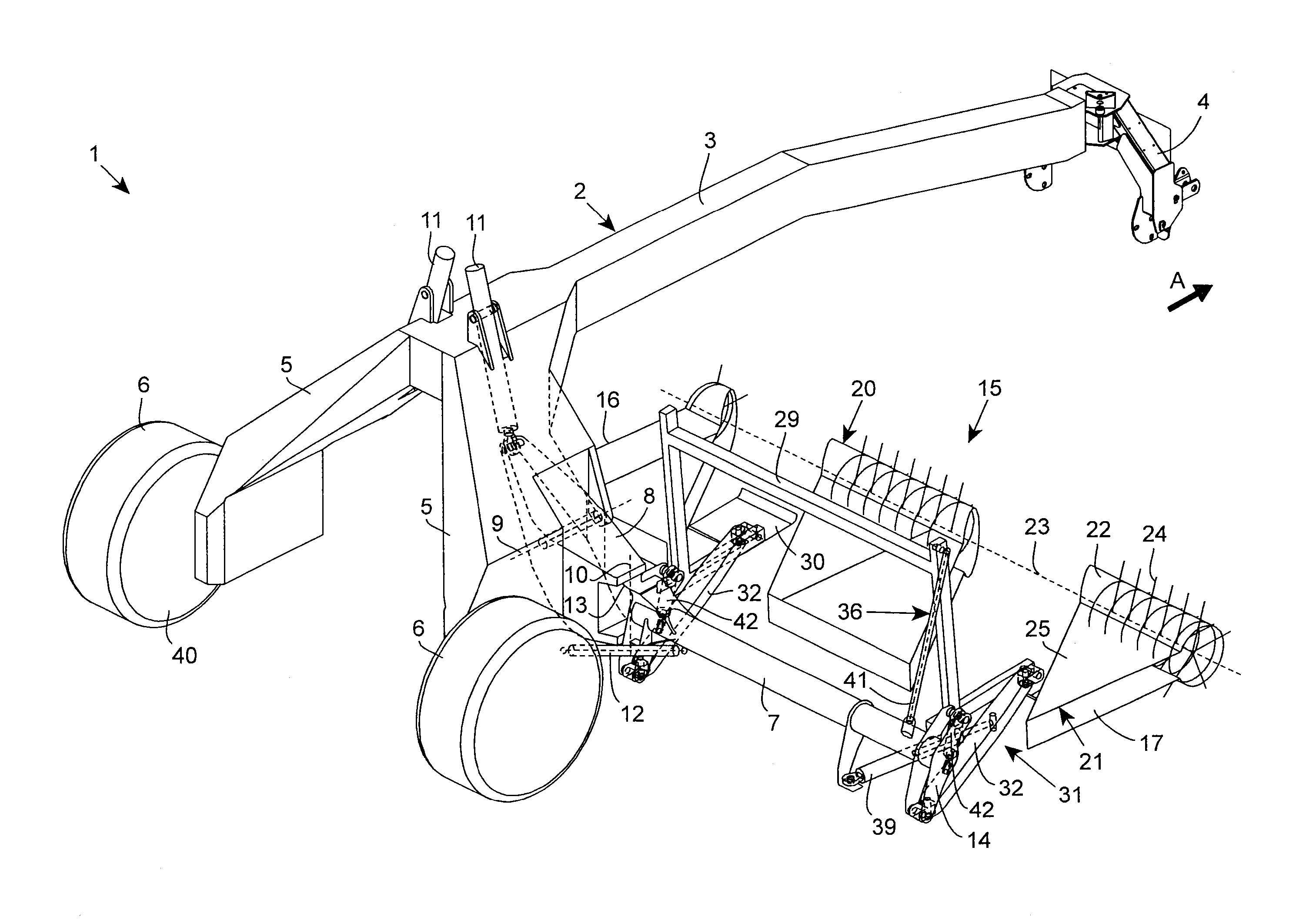
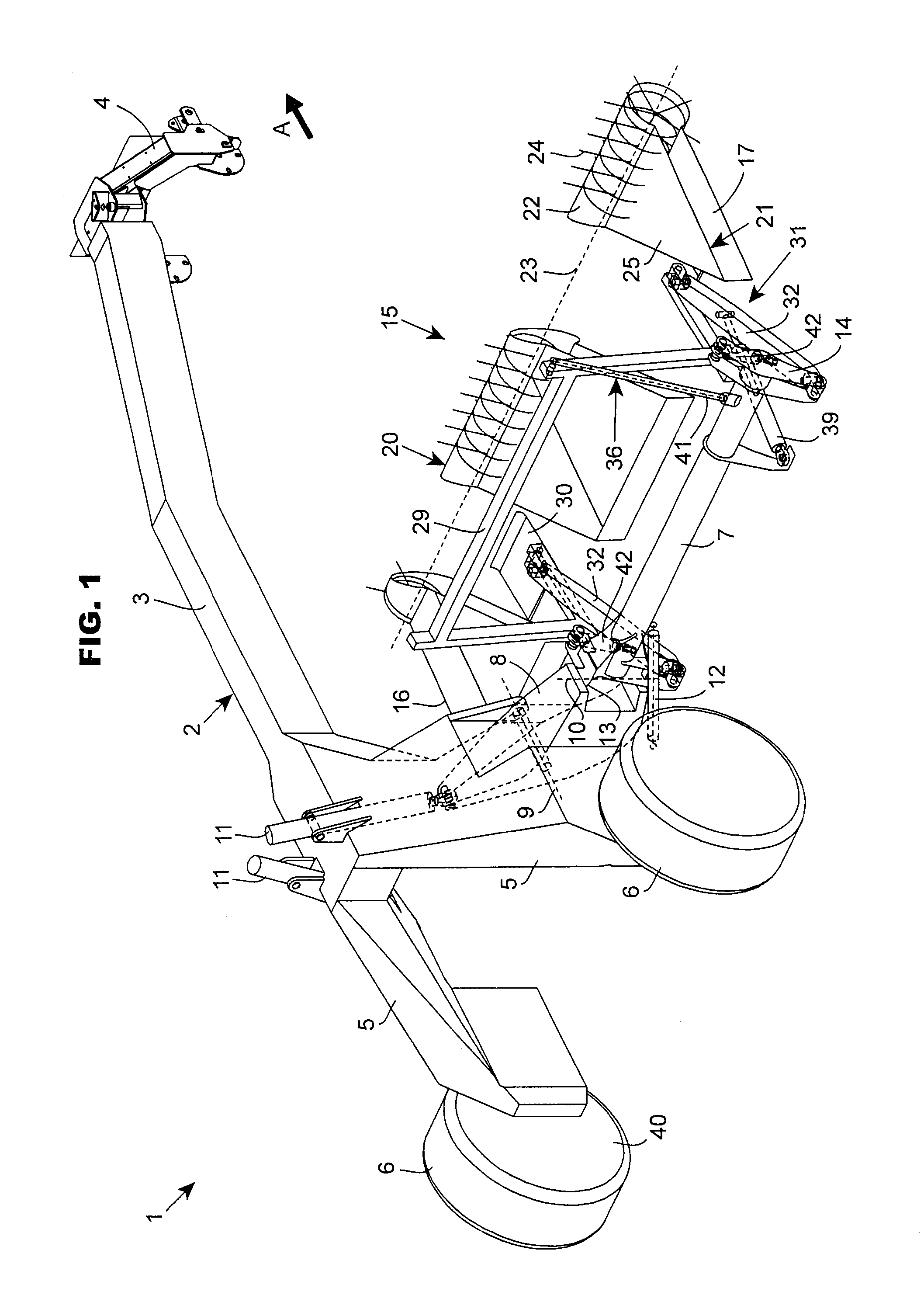
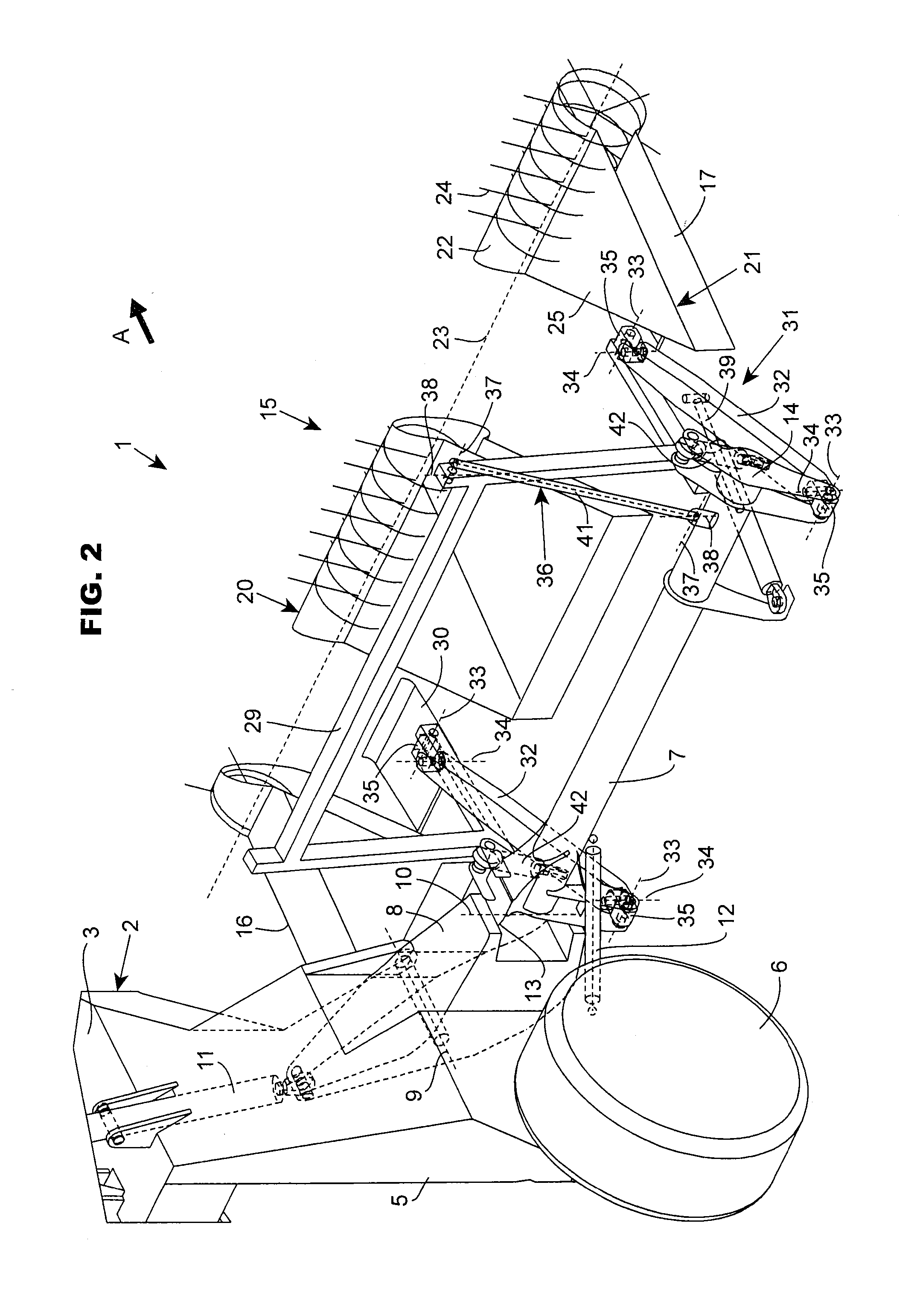
[0025]The machine 1 according to the invention is an agricultural machine for the harvesting of plants, in particular of fodder. This machine 1 comprises a chassis 2. As can be seen from FIG. 1, this includes a central beam 3 which has at its front end a hitching device 4 for hitching it to a tractor T allowing the machine to be moved in a direction of advance A. In the following description, the terms “front”, “rear”, “rearwards”, “downstream”, “behind”, “left” and “right” are defined with respect to the direction of advance A, whilst the terms “upwards”, “upper”, “above”, “lower” and “beneath” relate to the ground. The central beam 3 extends along the direction of advance A. In its rear part, the central beam 3 carries lateral posts 5 which extend in the direction of the ground. The chassis 2 is supported on the ground by wheels 6. Each wheel 6 is carried by a respective lateral post 5. At least one support arm 7 is articulated on the chassis 2, which support arm is carried by a l...


PUM


Abstract

A machine for the harvesting of plants, movable in a direction of advance, comprises an arm movable between work and transport configurations, a tool comprising lateral ends and being able to occupy a work position and another position, a connecting device via which the tool is connected to the arm and enabling a first movement of the tool relative to the arm, during which the lateral ends move vertically relative to the arm in the same vertical direction relative thereto, the connecting device comprising means making it possible to operate a second transverse and horizontal movement of the tool relative to the arm and making it possible to operate this second movement independently of the first movement. The connecting device comprises an arm oriented in the direction of advance when the support arm is in the work configuration, this arm is articulated on the support arm about a first transverse and horizontal axis when the support arm is in the work configuration, and this arm can, by pivoting about the first axis, move vertically relative to the support arm in the work configuration.

Description

BACKGROUND OF THE INVENTION[0001]1. Field of the Invention[0002]The present invention relates to an agricultural machine for the harvesting of plants, in particular of fodder, this machine being movable in a direction of advance and comprising in particular:[0003]a chassis,[0004]at least one support arm articulated on the chassis and movable with respect to the chassis between a work configuration in which the support arm extends laterally with respect to the chassis, and a transport configuration in which the support arm is folded such that its overall dimension perpendicularly to the direction of advance (A) is reduced,[0005]at least one work tool comprising an inner lateral end and an outer lateral end, and being able to occupy at least one work position in which the work tool acts on plants lying on the ground, and at least another position,[0006]a connecting device, by means of which a frame of the work tool is connected to the support arm, this connecting device allowing, at l...

Claims


Application Information

Patent Timeline
IPC IPC(8): A01D78/00A01B73/02
CPCA01D78/001A01B73/02A01B63/24A01D87/02A01B63/32A01D84/00A01B73/044A01D78/14
Inventor SCHWER, MICHAELWILHELM, JOEL
Owner KUHN SA
Why Eureka
Try Eureka