

Terminal-attached electric wire
- Summary
- Abstract
- Description
- Claims
- Application Information
AI Technical Summary
Benefits of technology
Problems solved by technology
Method used
Image

Examples
first embodiment
[0030]Terminal-Attached Electric Wire:
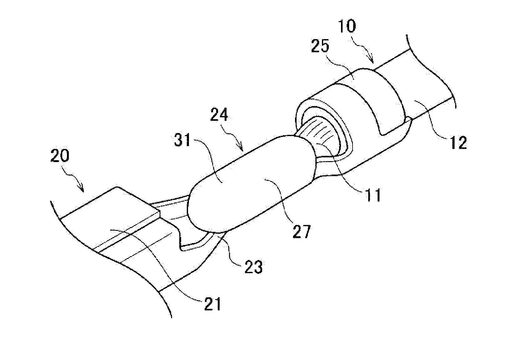
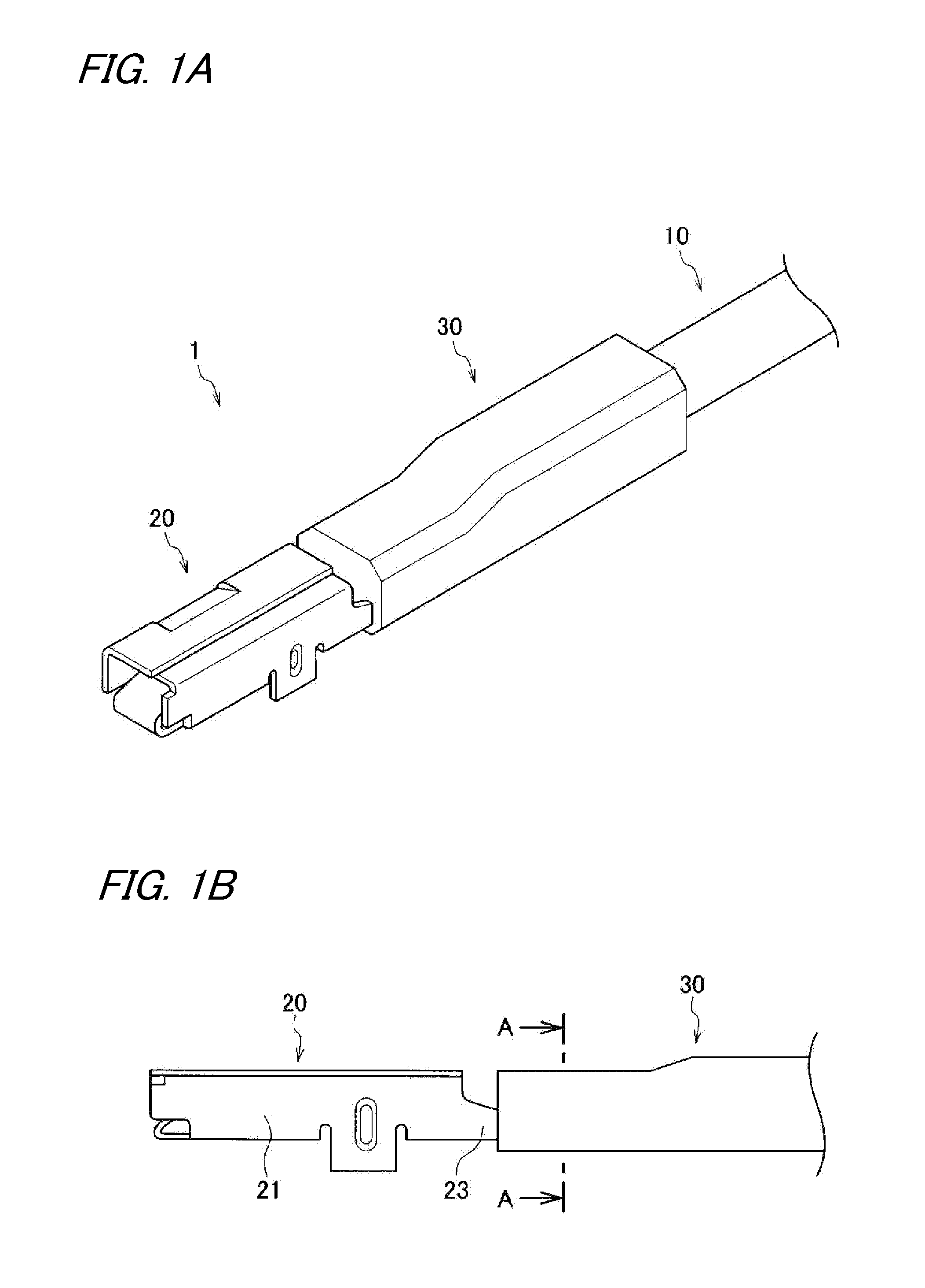
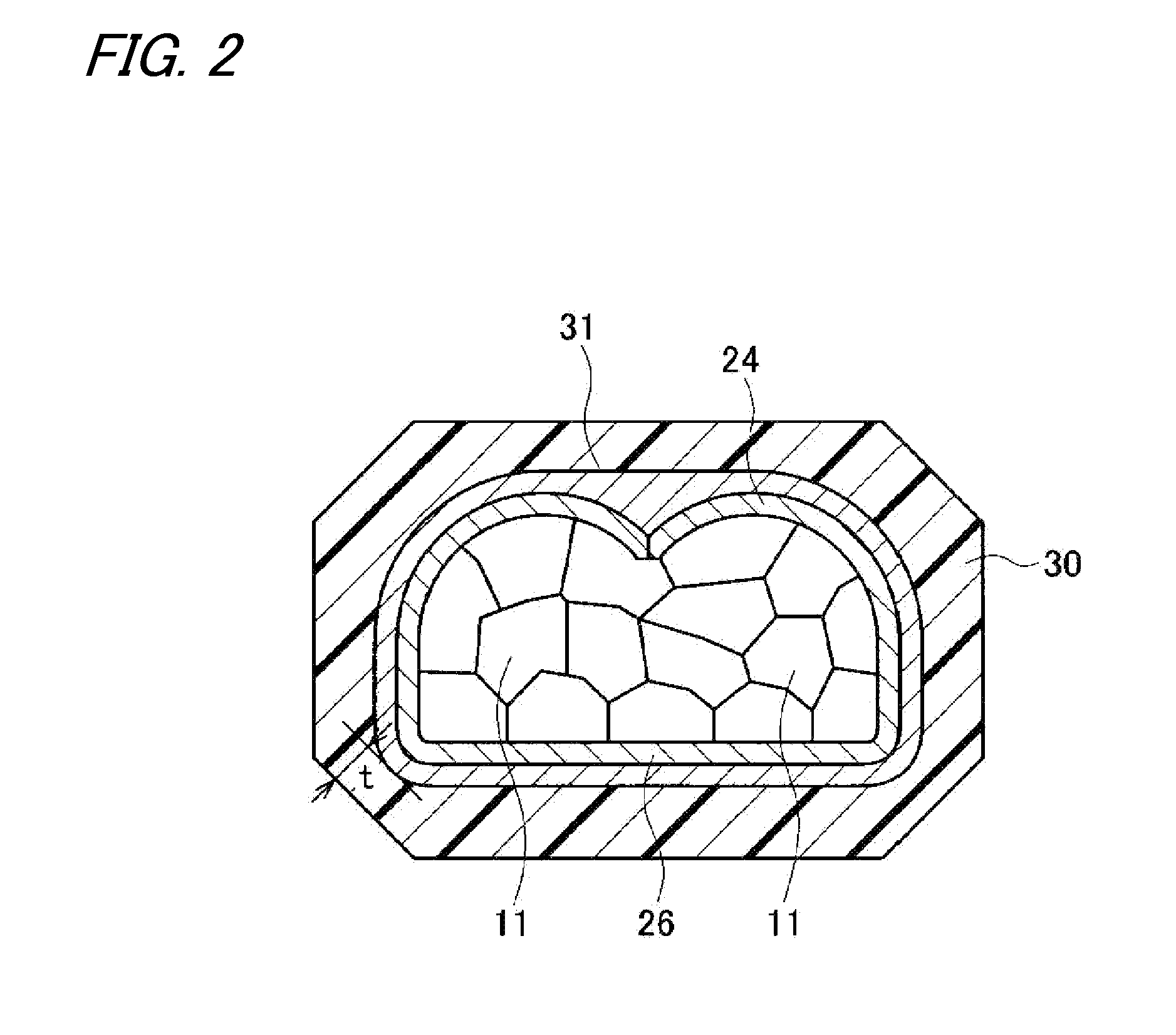
[0031]As shown in FIGS. 1 to 4, a terminal-attached electric wire 1 according to this embodiment includes an electric wire 10 having a conductor 11 and an electric wire cover member 12, and a crimping terminal 20 connected to the conductor 11 of the electric wire 10. The terminal-attached electric wire 1 further includes a corrosion resistant member 30 which is integrally formed with a peripheral portion of a joint section interposed between the conductor 11 and the crimping terminal 20 and a peripheral portion of the electric wire cover member 12 adjacent to the joint section. In addition, a primer 31 is provided at an interspace between the corrosion resistant member 30 and the joint section interposed between the conductor 11 and the crimping terminal 20.
[0032]The crimping terminal 20 on the terminal-attached electric wire 1 is of a female type and has, at its front portion, an electric connection section 21 to be connected to a counter termi...
second embodiment
[0069]Now, referring to the drawings, a terminal-attached electric wire according to the second embodiment of the present invention will be described in detail. The components which are substantially identical with or similar to those of the first embodiment are denoted by the same reference numerals, and duplicated description is omitted.
[0070]FIG. 8 is a cross sectional view of a terminal-attached electric wire according to this embodiment. As shown in FIGS. 1A, 1B, 3, 4 and 8, a terminal-attached electric wire 1 according to this embodiment includes an electric wire 10 having a conductor 11 and an electric wire cover member 12, and a crimping terminal 20 connected to the conductor 11 of the electric wire 10. The terminal-attached electric wire 1 further includes a corrosion resistant member 30 which is integrally formed with a peripheral portion of a joint section interposed between the conductor 11 and the crimping terminal 20 and a peripheral portion of the electric wire cover ...
examples
[0085]The invention is described below in detail on the basis of practical examples and comparison examples. However, the invention is not limited by the practical examples.
PUM
| Property | Measurement | Unit |
|---|---|---|
| Peel strength | aaaaa | aaaaa |
| Fracture energy | aaaaa | aaaaa |
Abstract
Description
Claims
Application Information