Operating method for membrane separation device and membrane separation device

Active Publication Date: 2015-01-22
KUBOTA LTD
View PDF1 Cites 7 Cited by
  • Summary
  • Abstract
  • Description
  • Claims
  • Application Information

AI Technical Summary

Benefits of technology

[0016]According to the aforementioned construction, the target value setting step increases the target value of the amount of the diffusion air from the membrane separation device when the transmembrane pressure difference is large, and decreases the target value of the amount of the diffusion air from the membrane separation device when the transmembrane pressure difference is small. In this target value setting step, the absolute value of the change or the rate of change in the target value set to increase the amount of the air diffusion is greater than the absolute value of the change or the rage of change in the target value set to decrease the amount of the air diffusion. Then the diffusion air amount control step controls the air diffusion device such that the amount of the diffusion air becomes the target value thereof. It should be noted that the transmembrane pressure difference means a pressure necessary to obtain filtered water, and is also referred to as filtration pressure difference, or TMP (Transmembrane Pressure).
[0017]When the transmembrane pressure difference is

Problems solved by technology

Conventionally, the amount of the diffused air supplied from the air diffusion device is set to exceed the minimum amount required for washing the membrane surface such that the separation membrane surface is not easily clogged even under a condition in which the separation membrane surface can otherwise be easily clogged by the influence of sludge properties or the like, which disadvantageously increases the cost of electrical power for air diffusing.
Considering the fact that approximately half of the operating cost required for treatment facilities employing the membrane bioreactor process is being spent on the air diffusion, it is an important issue to reduce the total amount of air diffusion while preventing the clogging of the separation membrane.
However, since the transmembrane pressure difference of the separation membrane tends to increase over t

Method used


Image

  • Operating method for membrane separation device and membrane separation device
  • Operating method for membrane separation device and membrane separation device
  • Operating method for membrane separation device and membrane separation device

Examples


Embodiment Construction

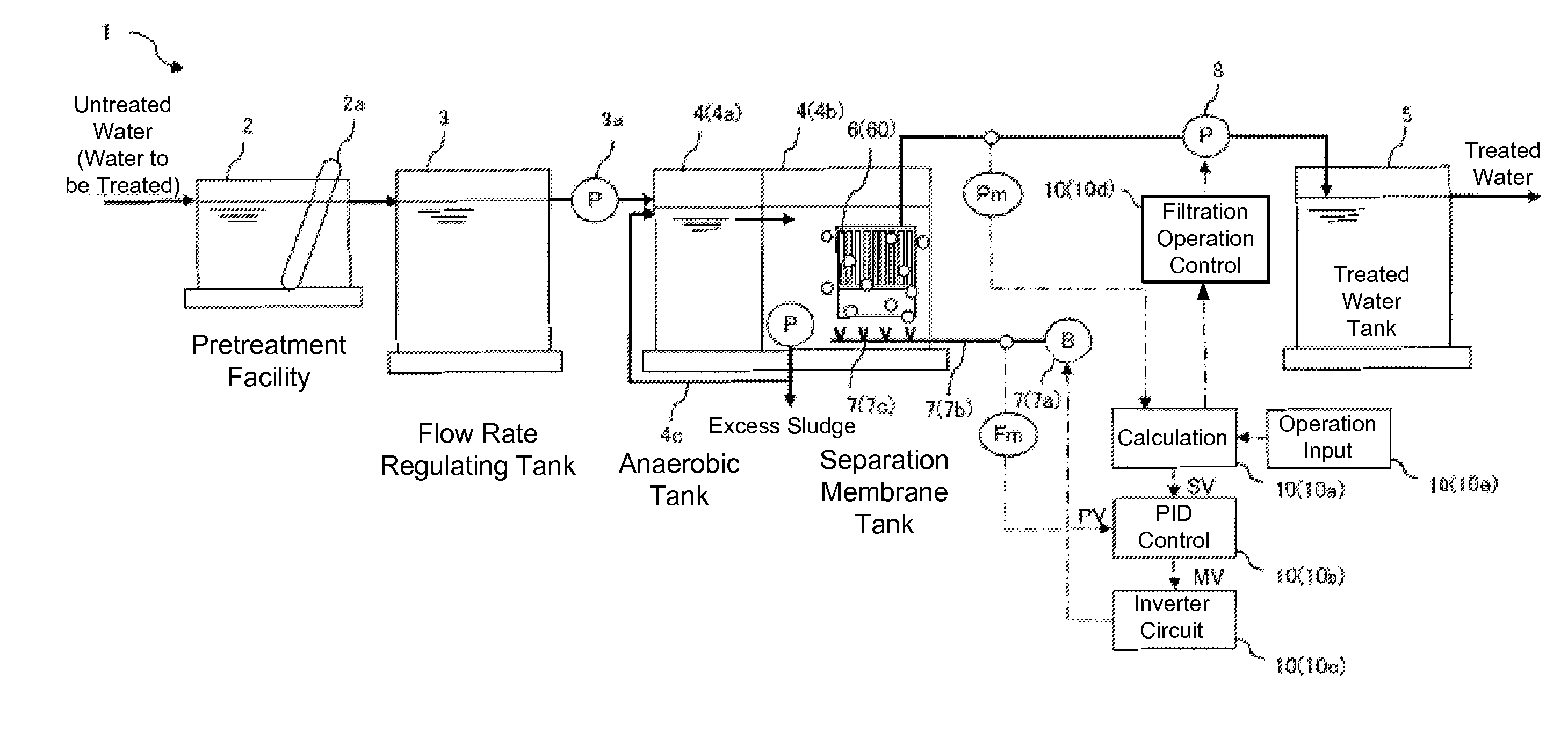
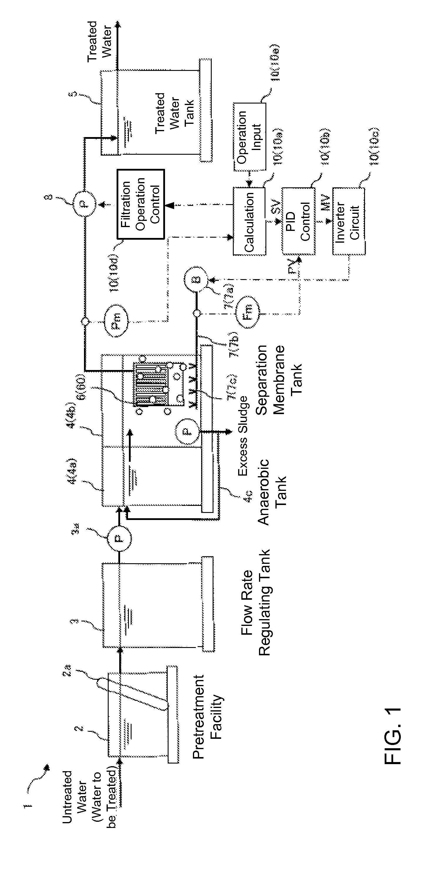
[0047]The membrane separation device and the operating method for the membrane separation device according to the present invention are described below. FIG. 1 illustrates an example of a wastewater treatment facility 1 provided with a membrane separation device 6. The wastewater treatment facility 1 includes a pretreatment facility 2, a flow rate regulating tank 3, an activated sludge treatment tank 4 having an anaerobic tank 4a and a separation membrane tank 4b filled with activated sludge, the membrane separation device 6 which is immersed in the separation membrane tank 4b so as to obtain permeated water from the water to be treated within the tank, and a treated water tank 5 which receives treated water filtered by the membrane separation device 6.

[0048]The pretreatment facility 2 is provided with a bar screen 2a or the like that removes foreign elements mixed in untreated water. After the foreign elements have been removed therefrom by the bar screen 2a or the like, the water ...


PUM

PropertyMeasurementUnit
Timeaaaaaaaaaa
Timeaaaaaaaaaa
Pressureaaaaaaaaaa

Abstract

A membrane separation device includes a separation membrane immersed in water to be treated and an air diffusion device positioned below the separation membrane, and provides treated water that has permeated through the separation membrane while diffusing air from the air diffusion device towards the separation membrane. A target value setting step sets a target value of an amount of diffusion air diffused from the air diffusion device based on a transmembrane pressure difference, and the air diffusion device is controlled such that the amount of the diffusion air becomes the target value. In the target value setting step, an absolute value of a change or a rate of change in the target value for increasing the amount of the air diffusion is set greater than an absolute value of a change or a rate of change in the target value for decreasing the amount of the air diffusion.

Description

CLAIM OF PRIORITY[0001]This application is a Continuation of International Patent Application No. PCT / JP2013 / 059179, filed on Mar. 28, 2013, which claims priority to Japanese Patent Application Nos. 2012-072917 and 2012-072916, both filed on Mar. 28, 2012, each of which is hereby incorporated by reference.BACKGROUND OF THE INVENTION[0002]1. Field of the Invention[0003]The present invention relates to a membrane separation device and a method for operating the same, where the membrane separation device includes a separation membrane immersed in water to be treated, and an air diffusion device positioned beneath the separation membrane, and provides treated water that has permeated through the separation membrane while diffusing air from the air diffusion device towards the separation membrane.[0004]2. Description of the Related Art[0005]Conventionally, a membrane bioreactor process has been widely used as a method for treating organic wastewater and the like (hereinafter called “wate...

Claims


Application Information

Patent Timeline
IPC IPC(8): B01D65/08C02F1/00B01D65/02C02F1/44
CPCB01D65/08C02F1/44C02F1/008B01D65/02C02F2209/03B01D2321/40B01D2321/185B01D61/147B01D61/16B01D61/22B01D2311/14B01D2315/06C02F3/006C02F3/1273C02F3/301C02F2203/002C02F2209/006C02F2209/38C02F2209/40C02F2303/16C02F2303/24Y02W10/10
Inventor YOSHIDA, YASUYUKIOHTSUKA, YUJI
Owner KUBOTA LTD
Why Eureka
Try Eureka