Method and Apparatus for Additively Manufacturing of Objects Based on Tensile Strength

a technology of additive manufacturing and tensile strength, applied in the direction of additive manufacturing process, manufacturing tools, mechanical vibration separation, etc., can solve the problem that the objects produced by prior art methods have the undesirable property of severe anisotropic tensile strength variation

Inactive Publication Date: 2015-01-22
MITSUBISHI ELECTRIC RES LAB INC
View PDF0 Cites 51 Cited by
  • Summary
  • Abstract
  • Description
  • Claims
  • Application Information

AI Technical Summary

Problems solved by technology

Generally, objects produced by prior art methods have the undesi

Method used


Image

  • Method and Apparatus for Additively Manufacturing of Objects Based on Tensile Strength
  • Method and Apparatus for Additively Manufacturing of Objects Based on Tensile Strength
  • Method and Apparatus for Additively Manufacturing of Objects Based on Tensile Strength

Examples


example

Pressure Tank

[0033]As shown in FIGS. 4A, 4B and 4C, a more interesting example object is a spherical pressure tank. For ease of this description, we ignore access holes and mounting hardware.

[0034]From a local perspective of a small part of tank wall material, each neighborhood looks identical. The stress tensor indicates that each small volume of tank wall is subject to uniform tension in all directions perpendicular to the radial direction of the tank. However, from a global perspective of view, the stress tensor varies with the latitude and longitude of each small Volume of tank material.

[0035]As shown in FIG. 4A, a patch at the “north pole” of the spherical tank experiences forces that are well-accommodated by an XY laydown path of a conventional XYZ 3D printer. However, the equator of the spherical tank is subject to a large tensile stress in the Z direction 404, which is as noted above as being very weak in a conventional 3D printer. This is because a conventional XYZ 3D print...


PUM

PropertyMeasurementUnit
Thicknessaaaaaaaaaa
Weight ratioaaaaaaaaaa
Strengthaaaaaaaaaa

Abstract

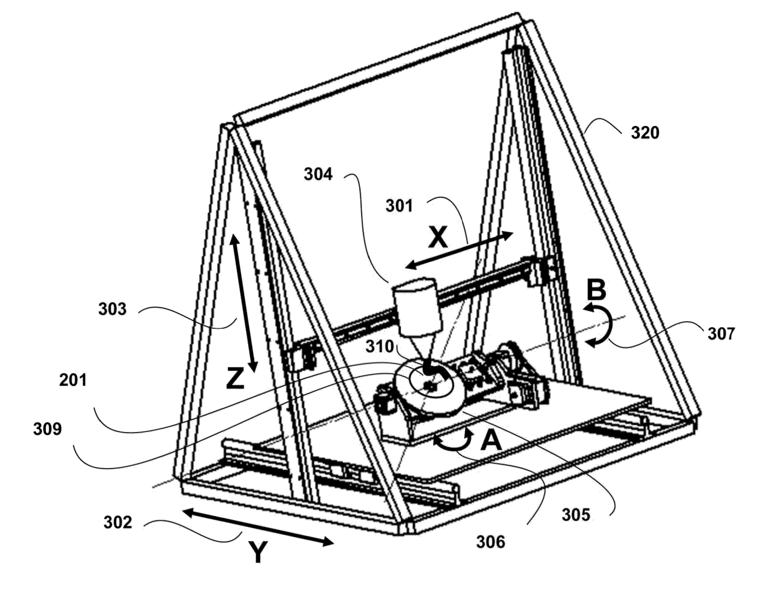
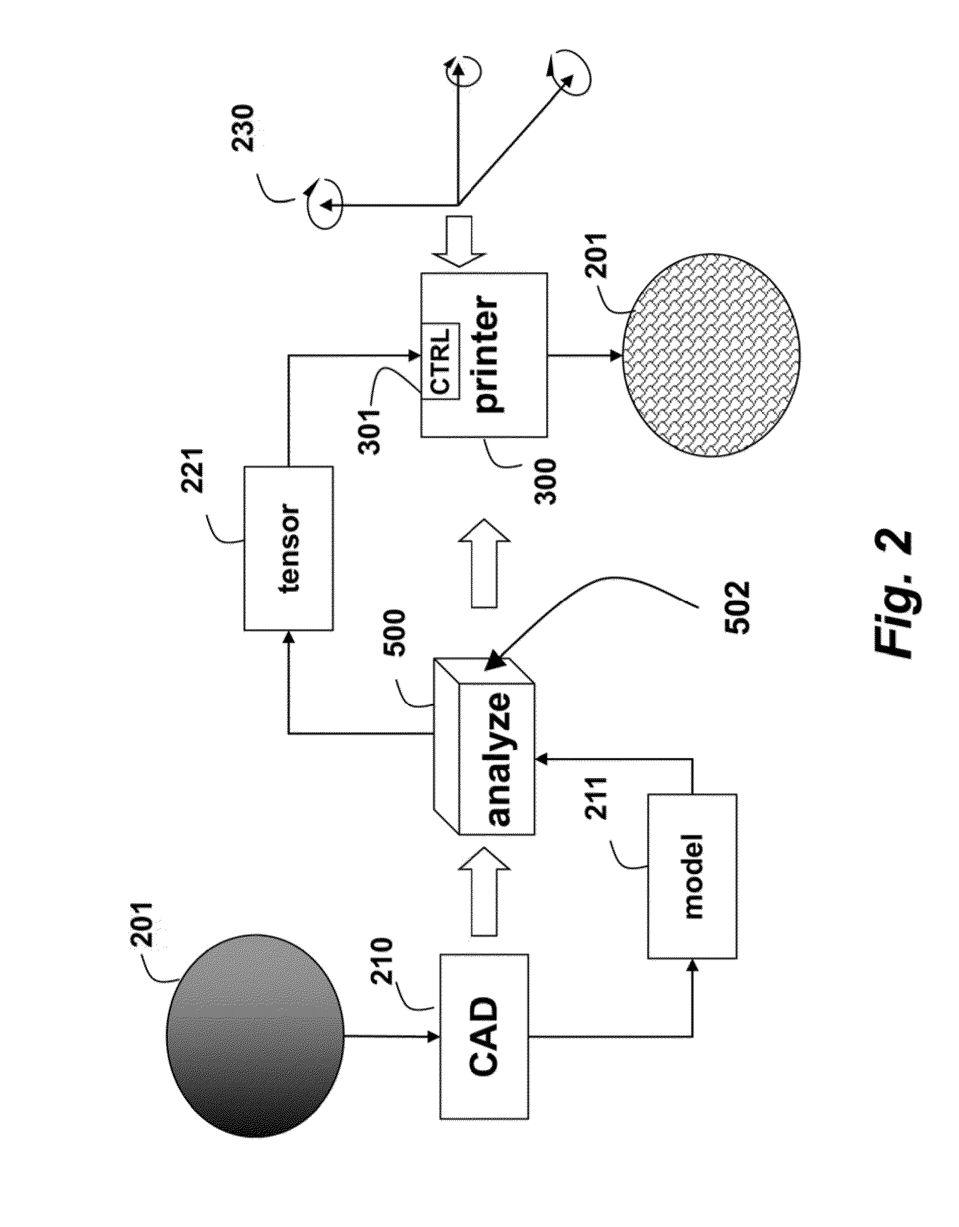
A 5D printer, which additively manufactures an object, includes an extruder that can move linearly along three orthogonal axes and rotationally around at least one of the axes with respect to the object while depositing a material. A gantry is movable along X, Y and Z axes, and a trunnion table movable about A and B axes is mounted on the gantry. A platen is mounted on the trunnion table, and the extruder deposits the material on the platen while moving the gantry and trunnion table. A model of the object is analyzed to produce a stress tensor for the object, and the depositing is according, to the stress tensor.

Description

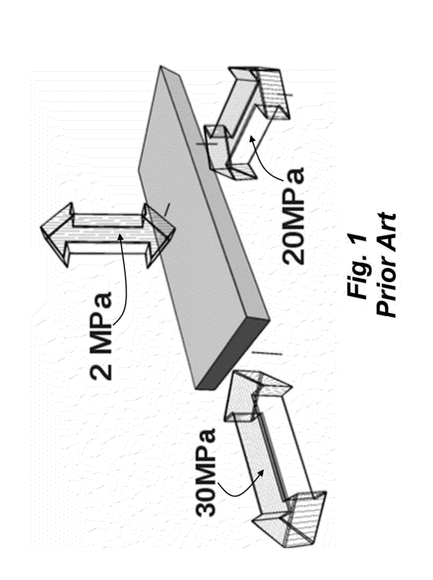
RELATED APPLICATION[0001]This application is related to U.S. application Ser. No. 13 / 945,223 cofiled herewith and incorporated by reference.FIELD OF THE INVENTION[0002]This invention relates generally to additive manufacturing objects, and more particularly provide the objects with a desired tensile strength.BACKGROUND OF THE INVENTION[0003]3D printing is an additive manufacturing process for making three-dimensional objects of arbitrary shapes from digital models. In 3D printing, successive layers of a material are laid down adjacently to form the objects. Typically, a round or ribbon like material is extruded through a movable nozzle.[0004]U.S. Pat. No. 5,121,329 describes fusion deposition modeling, wherein an extruder is moved in a rectangular coordinate system while producing a stream or ribbons of melted thermoplastic material. The ribbons are laid down, adjacent to each other to produce layers that fill the volume of the desired object.[0005]U.S. Pat. No. 5,866,058 describes ...

Claims


Application Information

Patent Timeline
IPC IPC(8): B29C67/00
CPCB29C67/0055B29K2995/0077B29C67/0088B29C64/106B29C64/393
Inventor YERAZUNIS, WILLIAM S.BARNWELL, III, JOHN C.KATZ, JOSEPHBRINKMAN, DIRK
Owner MITSUBISHI ELECTRIC RES LAB INC
Why Eureka
Try Eureka