
Solar Powered Wind Turbine Apparatus For Reducing Or Eliminating Wind Cut-in Speed

a wind turbine and solar energy technology, applied in wind turbines with solar radiation, electric generator control, greenhouse gas reduction, etc., can solve the problems of low electric power production, and non-rotation of wind turbine blades

Inactive Publication Date: 2015-01-22
LEE WILLIAM EDWARD +1
View PDF3 Cites 9 Cited by
  • Summary
  • Abstract
  • Description
  • Claims
  • Application Information

AI Technical Summary

Benefits of technology

The patent is about a solar powered wind turbine that can generate power even when the wind is not very strong. The turbine has a solar dome that collects sunlight and a motor that uses the sunlight to rotate the blades of the turbine. This eliminates the need for a minimum wind speed to start the turbine. The solar dome can be moved to different positions on the turbine to maximize sunlight collection. The solar dome also cools the photovoltaic cells, increasing their efficiency. Overall, this invention allows for more efficient and reliable power generation from wind and sunlight.

Problems solved by technology

Sometimes, the wind does not attain the cut-in speed, resulting in non-rotation of the blades of the wind turbine and therefore non-generation of electric power.
This dependency on attainment of the cut-in speed by the wind speed reduces the power that is generated by the wind turbine resulting in low electric power production.
Hence, there is a long felt but unresolved need for a method and an apparatus that provides power to rotate the blades of a wind turbine when the wind speed is less than the cut-in speed, thereby reducing or eliminating a cut-in speed required to rotate the blades of the wind turbine.

Method used


Image

  • Solar Powered Wind Turbine Apparatus For Reducing Or Eliminating Wind Cut-in Speed
  • Solar Powered Wind Turbine Apparatus For Reducing Or Eliminating Wind Cut-in Speed
  • Solar Powered Wind Turbine Apparatus For Reducing Or Eliminating Wind Cut-in Speed

Examples


Embodiment Construction

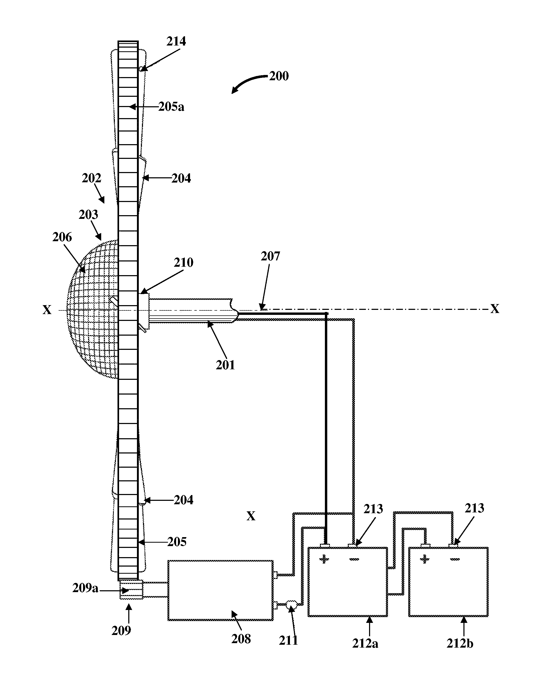
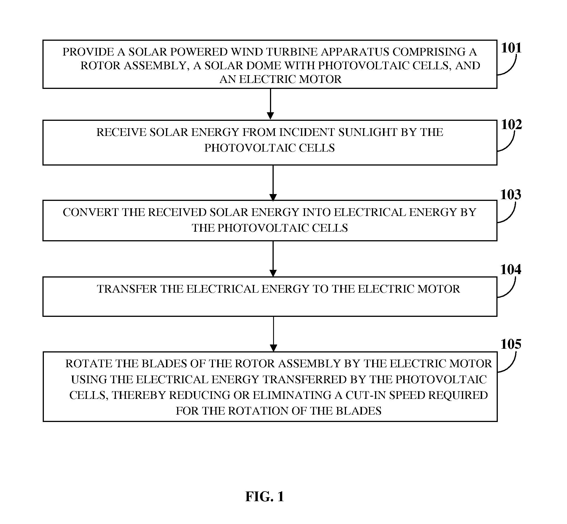
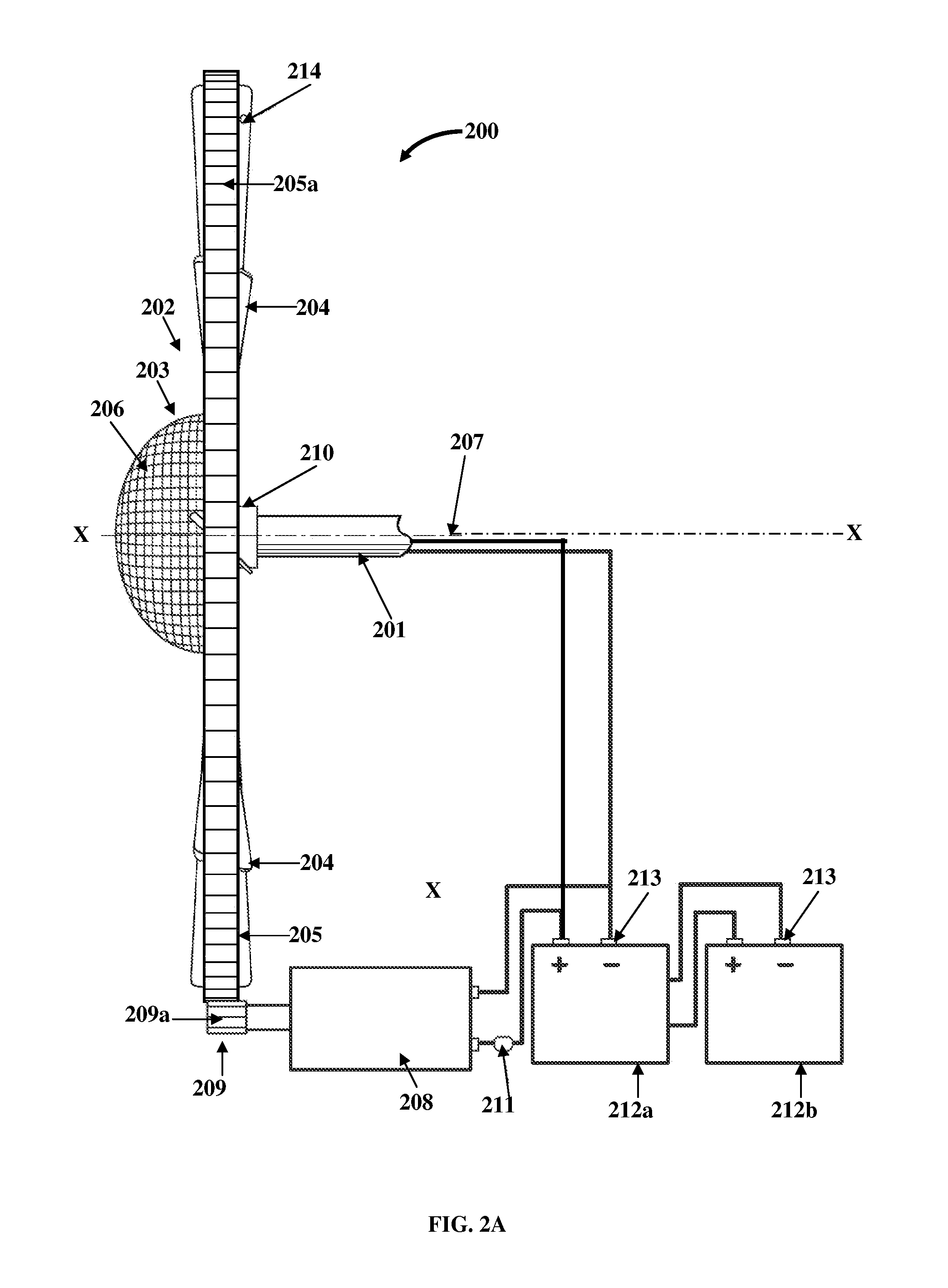
[0015]FIG. 1 illustrates a method for initiating rotation of blades 204 of a wind turbine 200 or 300 exemplarily illustrated in FIGS. 2A-2B and FIGS. 3A-3B, when the speed of wind is less than a cut-in speed, thereby reducing or eliminating the cut-in speed requirement of the wind turbine 200 or 300. As used herein, the term “cut-in speed” refers to a minimum speed of wind at which the blades 204 of a wind turbine 200 or 300 start rotating in response to power from the wind or an alternative source. By way of example, consider a wind turbine 200 or 300 that has a cut-in speed of 5 miles per hour. When the speed of the wind traversing the wind turbine 200 or 300 is, for example, from 0 miles per hour to any speed less than 5 miles per hour, the blades 204 of the wind turbine 200 or 300 will not rotate. When the wind speed traversing the wind turbine 200 or 300 reaches 5 miles per hour, the blades 204 of the wind turbine 200 or 300 will start rotating. In this example, the method disc...


PUM


Abstract

A method and an apparatus are provided for initiating rotation of blades of a wind turbine when wind speed is less than a cut-in speed. A solar powered wind turbine apparatus includes a solar dome with photovoltaic cells, operably connected to a rotor assembly, and an electric motor. The photovoltaic cells convert solar energy from incident sunlight into electrical energy. The electric motor electrically connected to the photovoltaic cells rotates the blades of the rotor assembly using the electrical energy from the photovoltaic cells. The electric motor powered by the photovoltaic cells initiates the rotation of the blades of the rotor assembly when wind speed is less than the cut-in speed, and therefore reduces or eliminates the cut-in speed required to rotate the blades. The blades of the rotor assembly thereafter continue to rotate in response to a force of wind on the blades and / or the powered electric motor.

Description

CROSS REFERENCE TO RELATED APPLICATIONS[0001]This application claims priority to and the benefit of provisional patent application No. 61 / 856,760 titled “Solar Powered Wind Turbine Apparatus With Reduced Cut-in Speed”, filed in the United States Patent and Trademark Office on Jul. 21, 2013. The specification of the above referenced patent application is incorporated herein by reference in its entirety.BACKGROUND[0002]Conventional wind turbines harness the energy of wind and convert the energy to a form of mechanical energy. The mechanical energy may further be converted to electrical energy based on the application in which the wind turbine is used. Nearly all conventional wind turbines require a minimum wind speed to rotate their blades. This wind speed is called a cut-in speed. As is known, power output of a wind turbine is directly proportional to a cube of the wind speed. Therefore, for example, about 10% increase in the wind speed results in about 33% increase of power output. ...

Claims


Application Information

Patent Timeline
Patent Type & Authority Applications(United States)
IPC IPC(8): H02K47/00H02K7/02F03D7/02F03D9/00
CPCF03D7/026F03D9/002H02K2213/06H02K7/025H02K47/00H02K7/183F05B2220/708F03D9/007H02K7/14Y02E10/50Y02E10/72Y02E70/30F03D9/11F03D9/12F03D9/25F03D15/10
Inventor LEE, WILLIAM EDWARDKRISHAN, BALDEV
Owner LEE WILLIAM EDWARD
Learn More