Projective capacitive stylus and controlling method thereof

a capacitive stylus and projective technology, applied in the direction of instruments, computing, electric digital data processing, etc., can solve the problems of life cycle problems, power consumption of this method is higher than that of a stylus with an energy storage device,

Active Publication Date: 2015-01-22
HENGHAO TECH CO LTD
View PDF15 Cites 8 Cited by
  • Summary
  • Abstract
  • Description
  • Claims
  • Application Information

AI Technical Summary

Benefits of technology

[0016]In accordance with the tenth aspect of the present invention, a controlling method for a projective capacitive stylus includes steps of: providing one of a conductor and an electric plate, configured on a tip of the stylus, and a winding electrically connected to the one of the conductor and the electric plate; and causing the one of the conductor and the electric plate to amplify a conductor effect via the winding so as to generate a relatively strong touch signal.

Problems solved by technology

In accordance with the aforementioned technology, if there is a power supply unit inside the stylus, regardless of the type of energy storage device, such as a rechargeable battery or a supercapacitor, used, it will need to be charged or replaced, which will cause a life-cycle problem.
If it is a passive electromagnetic stylus, the host needs to release an electromagnetic field with high energy to allow the stylus to induce this energy in order to operate, and the power consumption of this method is higher than that of a stylus with an energy storage device.

Method used


Image

  • Projective capacitive stylus and controlling method thereof
  • Projective capacitive stylus and controlling method thereof
  • Projective capacitive stylus and controlling method thereof

Examples


embodiment 1

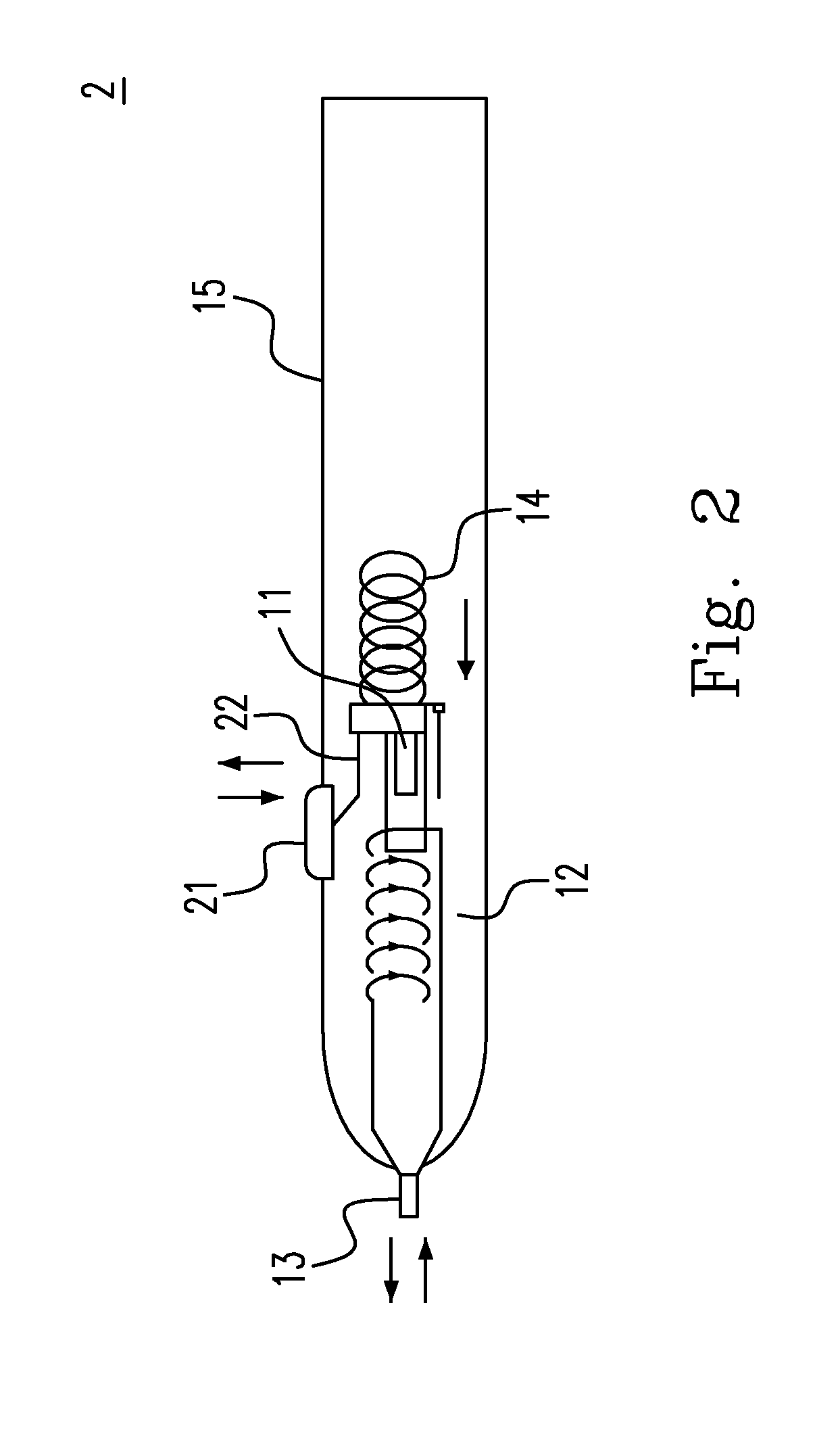
[0044]2. A projective capacitive stylus , further comprising a button, and a connecting rod connected to the button and the magnet, wherein when the button is pressed, the external force generated thereby causes the connecting rod to move inward to drive the first terminal of the magnet to depart from the winding so as to generate an induced reversal potential, which causes the second current to be generated on the winding; and when the button is released from being pushed-down, the external force is removed, causing the spring to push the magnet back to the original position to generate an induced potential at this moment, which in turn causes the first current to be generated on the winding.

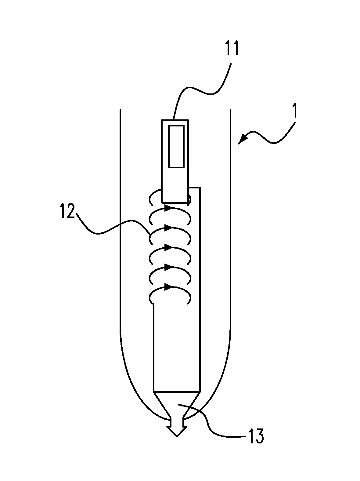
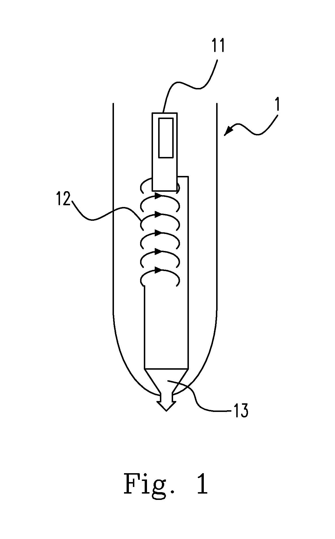
[0045]3. A projective capacitive stylus according to Embodiment 1 or 2, further comprising a shell containing the magnet, the winding, the spring and the one of the conductor and the electric plate, wherein the shell has a tip end and a top end, the tip end has an opening allowing the one of th...


PUM


Abstract

Configurations of a stylus and controlling methods thereof are disclosed. The proposed stylus causes a touch panel to generate a signal by an electrical field generated by a magnetic field via one of a conductor and an electric plate, wherein the stylus includes a set of windings and a magnet, which can move towards each other and generate a current on the set of windings through interaction. The current flows through the conductor / electric plate on a tip of the stylus to generate one of an electric flux line and a magnetic flux line such that the touch panel can sense the movement of the stylus.

Description

CROSS-REFERENCES TO RELATED APPLICATIONS[0001]This application claims the benefits of Taiwan Patent Application Number 102125640 filed on Jul. 17, 2013, at the Taiwan Intellectual Property Office, the disclosures of which are incorporated herein in their entirety by reference.FIELD OF THE INVENTION[0002]The present invention relates to a projective capacitive stylus and a controlling method thereof, in particular to a projective capacitive stylus used for a projective capacitive touch panel.BACKGROUND OF THE INVENTION[0003]According to the prior arts, a stylus is required to have a power supply, or an externally transmitted induced electrical field to supply energy such that the stylus could be operated after obtaining the energy, and this stylus can only be used in electromagnetic touch technology. In accordance with the aforementioned technology, if there is a power supply unit inside the stylus, regardless of the type of energy storage device, such as a rechargeable battery or a ...

Claims


Application Information

Patent Timeline
Patent Type & Authority Applications(United States)
IPC IPC(8): G06F3/0354G06F3/044
CPCG06F3/044G06F3/03545G06F3/0441G06F3/0442
Inventor KUO, MING-SHAN
Owner HENGHAO TECH CO LTD
Why Eureka
Try Eureka