Liquid ejecting apparatus and method of controlling liquid ejecting apparatus

a technology of liquid ejecting apparatus and liquid ejecting apparatus, which is applied in the direction of printing, etc., can solve the problems of weak crystal silicon substrate, difficult to make uniform ejecting characteristics of the end, and rigid partition wall in a case where the pressure chamber is formed

Active Publication Date: 2015-01-22
SEIKO EPSON CORP
View PDF1 Cites 2 Cited by
  • Summary
  • Abstract
  • Description
  • Claims
  • Application Information

AI Technical Summary

Benefits of technology

[0010]An advantage of some aspects of the invention is to provide a liquid ejecting apparatus which can make uniform the ejection characteristics of each linearly aligned pressure chamber, and a method of controlling the liquid ejecting apparatus.
[0013]In this case, during the period in which the ejection of the liquid from the nozzle in at least a pressure chamber adjacent to the dummy pressure chamber is performed, the drive potential is continuously applied to the piezoelectric element corresponding to the dummy pressure chamber, thus the piezoelectric element is tensed to support the partition wall between the pressure chamber adjacent to the dummy pressure chamber and the dummy pressure chamber from the side. As a result, even if an internal pressure of the adjacent pressure chamber increases, the partition wall is suppressed from being deformed (bent) toward the dummy pressure chamber side. Due to this, it is possible to reduce pressure loss toward the dummy pressure chamber side from the pressure chamber adjacent to the dummy pressure chamber. Since the partition wall is supported by the tense piezoelectric element, the rigidity of the partition wall is not excessively great, when compared with a configuration (configuration in which a portion corresponding to the dummy pressure chamber is a wall having a greater rigidity than that of the partition wall) in which the dummy pressure chamber is not provided. Thus, it is possible to make uniform a deformation degree of the partition wall on the dummy pressure chamber side and a deformation degree of the partition wall on the other pressure chamber side to the same degree, when the pressure variation occurs in the pressure chamber adjacent to the dummy pressure chamber. As a result, it is possible to make uniform the pressure loss due to a propagation of the pressure variation to the same degree as in other pressure chambers, regardless of the position of the pressure chamber. As a result, it is possible to make uniform characteristics of the ejection of the liquid of each pressure chamber in the pressure chamber array. Due to this, it is possible to cope with a high density of the nozzles (pressure chambers) or miniaturization of the liquid ejecting head. In addition, it is suitable in a case where a substrate which forms the pressure chamber is produced by materials with a relatively weak rigidity such as a single crystal silicon substrate.
[0015]In this case, since the drive potential which is applied to the piezoelectric element of the dummy pressure chamber is the reference potential which has an ejection drive waveform and causes the piezoelectric element of other pressure chambers to perform the ejection of the liquid, it is possible to average approximately the rigidities of the partition walls on both sides of the pressure chamber adjacent to the dummy pressure chamber, and to easily make uniform the ejection characteristics, regardless of the ejection or non-ejection of the liquid in a pressure chamber adjacent to the pressure chamber adjacent to the dummy pressure chamber.
[0017]In this case, the pressure chamber array is divided into a plurality of pressure chamber arrays and the dummy pressure chamber is formed on both sides of each pressure chamber array, and thus, configuring in such a manner that liquids of types different from each other flow into each pressure chamber is suitable. That is, it is not necessary to provide a dedicated nozzle array (pressure chamber array) or a dedicated liquid ejecting head for each liquid type, and it is possible to cope with multiple types of liquids with one nozzle array (pressure chamber array).
[0021]In this case, the liquid is filled into the dummy pressure chamber in the same manner as in other pressure chambers, and thus, it is possible to make uniform contraction stress on the liquid in the dummy pressure chamber with contraction stress on the liquid in each pressure chamber, when the pressure variation occurs in the pressure chamber adjacent to the dummy pressure chamber. Due to this, it is possible to make uniform more reliably the ejection characteristics of each pressure chamber.

Problems solved by technology

The rigidity of the partition wall in a case where the pressure chamber is formed by a single crystal silicon substrate is weak, when compared with that of a metal such as stainless steel.
Due to circumstances such as these, there have been lots of cases where it has been difficult to make uniform ejection characteristics of the end portion pressure chambers and pressure chambers on the inside at the time of the ejection of the liquid, only by simply providing a dummy pressure chamber.
In addition, such a problem exists not only in an ink jet type recording apparatus on which a recording head that ejects ink is mounted, but also in other liquid ejecting apparatuses which eject liquid from a nozzle by generating a pressure variation in the liquid in a pressure chamber.

Method used


Image

  • Liquid ejecting apparatus and method of controlling liquid ejecting apparatus
  • Liquid ejecting apparatus and method of controlling liquid ejecting apparatus
  • Liquid ejecting apparatus and method of controlling liquid ejecting apparatus

Examples


Embodiment Construction

[0032]Hereinafter, embodiments of the invention will be described with reference to the attached drawings. In addition, in the embodiments described below, various limitations are made as preferable specific examples of the invention, but if there is no description to the effect that the invention is particularly limited in the following description, the scope of the invention is not limited thereto. In addition, in the following description, an ink jet type recording apparatus (hereinafter, printer) will be described as an example of a liquid ejecting apparatus of the invention.

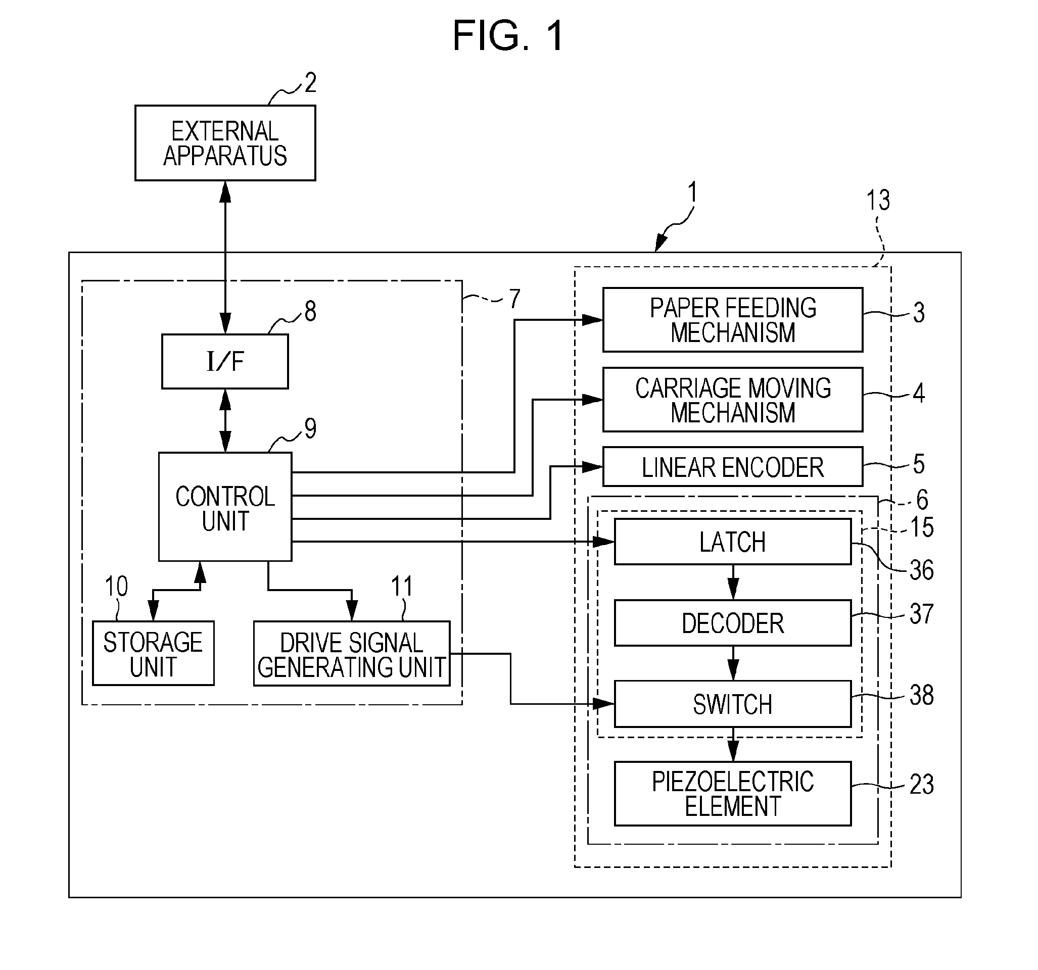
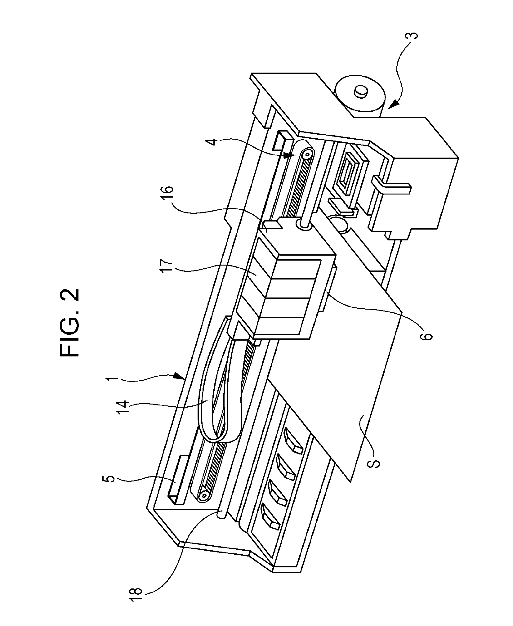
[0033]FIG. 1 is a block diagram for explaining an electrical configuration of a printer 1, and FIG. 2 is a perspective view for explaining an internal configuration of the printer 1. An external apparatus 2 is an electronic device such as a computer, a digital camera, a mobile phone, or a portable information terminal. The external apparatus 2 is electrically connected to the printer 1 wirelessly or in a wir...


PUM


Abstract

A pressure chamber array includes one or more dummy pressure chambers in which ejection of ink is not performed, the dummy pressure chamber includes a piezoelectric element, and a drive potential generator continues to apply a drive potential to the piezoelectric element corresponding to the dummy pressure chamber, while the ejection of the ink from a nozzle of at least a pressure chamber adjacent to the dummy pressure chamber is performed.

Description

CROSS-REFERENCE TO RELATED APPLICATIONS[0001]The present application claims priority to Japanese Patent Application No. 2013-150109 filed on Jul. 19, 2013, and Japanese Patent Application No. 2013-220729 filed on Oct. 24, 2013, which applications are hereby incorporated by reference in their entirety.BACKGROUND[0002]1. Technical Field[0003]The present invention relates to a liquid ejecting apparatus such as an ink jet type recording apparatus, and a method of controlling the liquid ejecting apparatus, and particularly to a liquid ejecting apparatus which drives a piezoelectric element by applying a drive potential to the piezoelectric element and thus causing liquid to be ejected from a nozzle, and a method of controlling the liquid ejecting apparatus.[0004]2. Related Art[0005]A liquid ejecting apparatus includes liquid ejecting heads, and is an apparatus which ejects (discharges) various liquids from the liquid ejecting heads. As the liquid ejecting apparatus, there is an image rec...

Claims


Application Information

Patent Timeline
Patent Type & Authority Applications(United States)
IPC IPC(8): B41J2/045
CPCB41J2/04581B41J2/0453B41J2/04593B41J2/04596B41J2/04588
Inventor FUKUDA, SHUNYA
Owner SEIKO EPSON CORP
Why Eureka
Try Eureka