Chip disposal device of machine tool

a technology of machine tools and disposal devices, which is applied in the direction of manufacturing tools, separation processes, filtration separation, etc., can solve the problems of low cutting fluid collection rate, insufficient fluid separation, and the reduction of the amount of cutting fluid discharged to the outside of the machine, so as to increase the total residence time of the chip lump, increase the collection amount of cutting fluid, and reduce the effect of the amount of cutting fluid

Inactive Publication Date: 2015-01-22
DMG MORI CO LTD
View PDF14 Cites 21 Cited by
  • Summary
  • Abstract
  • Description
  • Claims
  • Application Information

AI Technical Summary

Benefits of technology

[0010]In the chip disposal device according to the present invention, the liquid separating part has the mounting part which continues from the inclined discharge surface and gets lower as it goes more apart outward from the inclined discharge surface, and the first chip lump conveyed onto the mounting part by the first scraping plate stays on the mounting part until it drops by being pushed by at least one second chip lump conveyed by at least one second scraping plate following the first scraping plate. Therefore, while the chip lump stays on the mounting part, the cutting fluid adhering to the chip lump is separated. This naturally means that a larger amount of the cutting fluid adhering to the chip lump is separated and collected as the chip lump stays longer. In this manner, a collection rate of the cutting fluid can be increased.
[0014]In the above-described suitable embodiment, the plural sets of the mounting part and the folded portion are provided in the stepped form and the chip lump stays and then moves sequentially on the mounting parts. Consequently, it is possible to greatly increase the total residence time of the chip lump on the mounting parts, which enables surer separation and collection of the cutting fluid, making it possible to increase a collection amount of the cutting fluid.

Problems solved by technology

A conventional chip disposal device of this type has a problem that a cutting fluid (coolant) supplied to a machining part of a workpiece is discharged out of the machine together with chips, which has given rise to a demand for a reduction of an amount of the cutting fluid discharged to the outside of the machine.
However, if the chips are only dropped from the conveyor to collide with the inclined surface as in the aforesaid conventional device, there is a possibility that the cutting fluid is not sufficiently separated and the cutting fluid is discharged while remaining on the chips, which has a problem of a low collection rate of the cutting fluid.

Method used


Image

  • Chip disposal device of machine tool
  • Chip disposal device of machine tool
  • Chip disposal device of machine tool

Examples


Embodiment Construction

[0020]Hereinafter, an embodiment of the present invention will be described based on the attached drawings.

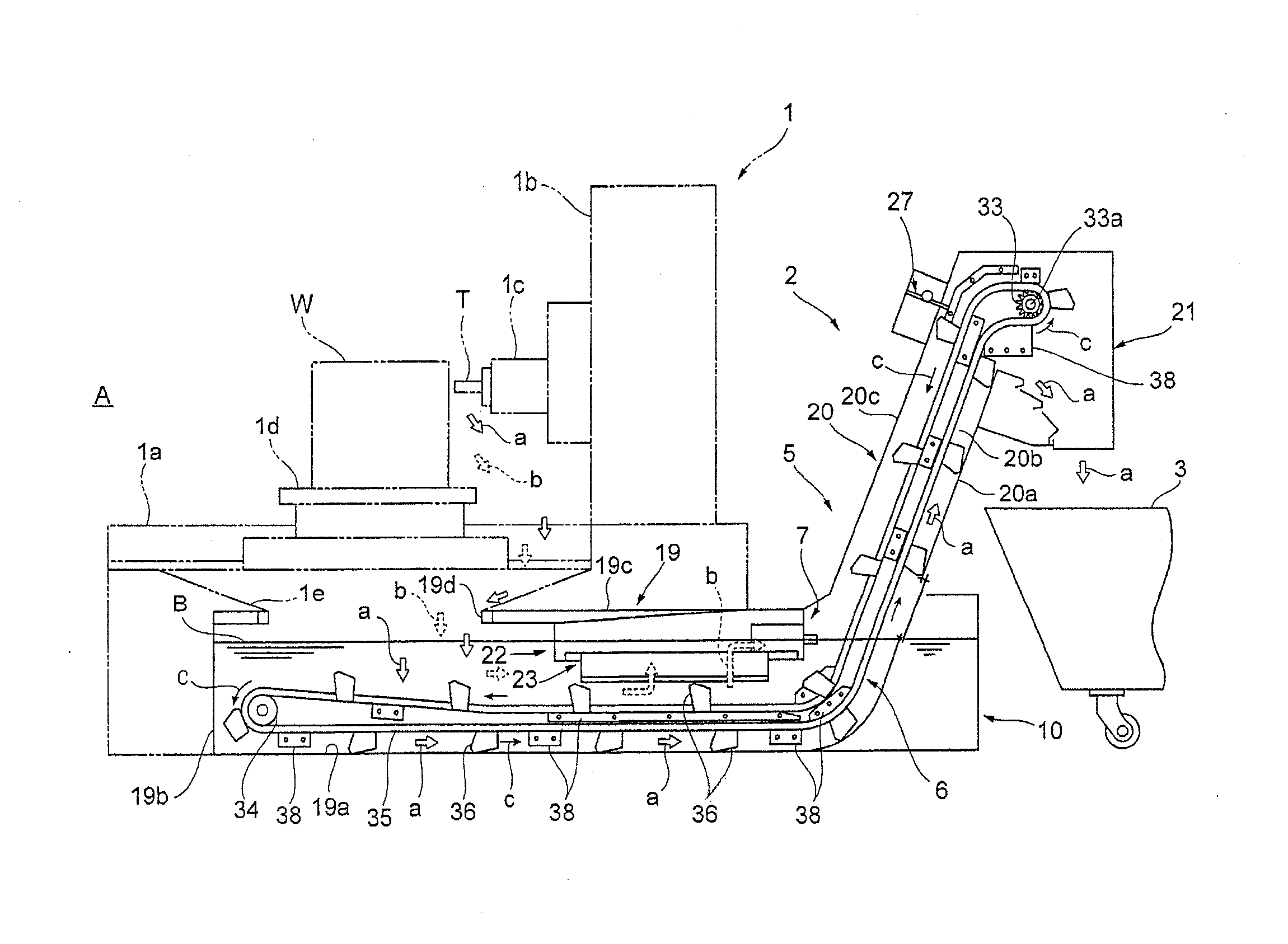
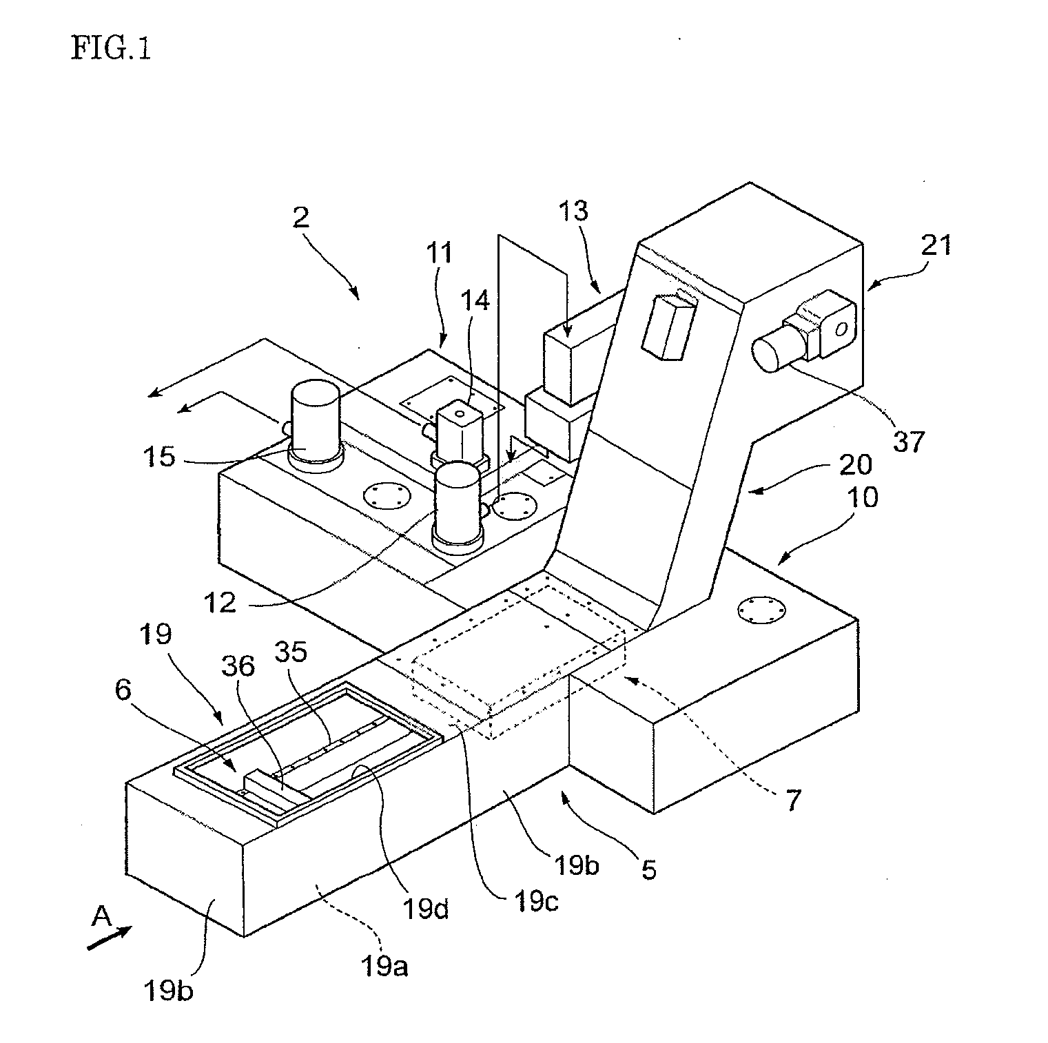
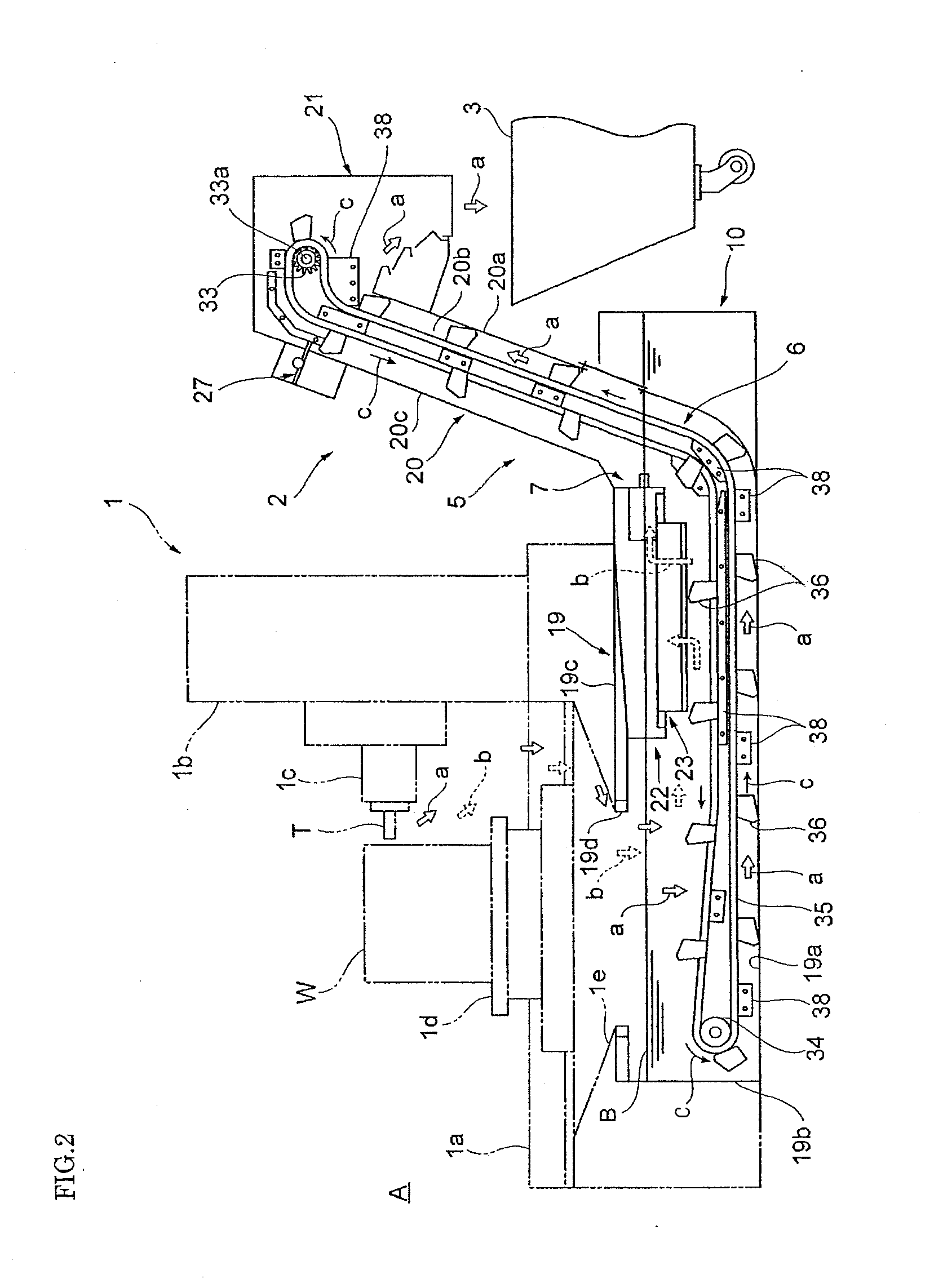
[0021]FIG. 1 to FIG. 5 are explanatory views of a chip disposal device of a machine tool according to the embodiment of the present invention. Front and rear, and left and right mentioned in this embodiment mean front and rear, and left and right in a state seen from a machine front.

[0022]In the drawings, 1 denotes a horizontal machining center as an example of a machine tool including a chip disposal device 2 of this embodiment (refer to FIG. 2).

[0023]This horizontal machining center 1 has: a column 1b disposed on a rear side of a bed 1a when seen from the machine front A; a spindle device 1c mounted on the column 1b; and a machining table 1d disposed on a center portion of the bed 1a, and applies a predetermined cutting work to a workpiece W mounted on the machining table 1d by a cutting tool T loaded to the spindle device 1c.

[0024]Under the machining table 1d of the bed 1a,...


PUM

PropertyMeasurementUnit
angleaaaaaaaaaa
surface tensionaaaaaaaaaa
residence timeaaaaaaaaaa

Abstract

To provide a chip disposal device of a machine tool which surely separates and collects a cutting fluid adhering to a chip lump, thereby capable of reducing an amount of the cutting fluid discharged to the outside of the machine. The chip disposal device includes a liquid separating part 65 which separates and collects a cutting fluid adhering to chips, the liquid separating part 65 has a mounting part 66 which is provided continuously from an inclined discharge surface 20a and is inclined so as to get lower as it goes more apart outward from the inclined discharge surface 20a, and to which a first chip lump a1 conveyed by a first scraping plate 36a is transferred. Then, the first chip lump a1 on the mounting part 66 stays on the mounting part 66 until dropping by being pushed by a second chip lump a2 conveyed by a second scraping plate 36b following the first scraping plate 36a.

Description

BACKGROUND OF THE INVENTION[0001]1. Field of the Invention[0002]The present invention relates to a chip disposal device of a machine tool which discharges chips produced by machining of a workpiece to the outside of the machine.[0003]2. Description of the Related Art[0004]A conventional chip disposal device of this type has a problem that a cutting fluid (coolant) supplied to a machining part of a workpiece is discharged out of the machine together with chips, which has given rise to a demand for a reduction of an amount of the cutting fluid discharged to the outside of the machine. For example, in Japanese Patent 3359014, chips conveyed by a conveyor are dropped onto an inclined surface inclined from a vertical plane by about 30 degrees, and the cutting fluid adhering to the chips is separated by the collision at the time of the dropping and is collected.[0005]However, if the chips are only dropped from the conveyor to collide with the inclined surface as in the aforesaid conventio...

Claims


Application Information

Patent Timeline
Patent Type & Authority Applications(United States)
IPC IPC(8): B23Q11/10B23Q11/00
CPCB23Q11/1069B23Q11/0067B23Q11/0057B01D33/04B01D43/00Y10T409/304088Y02P70/10
Inventor MATSUYAMA, TOMOYOSHIKAKUTANI, MASAHIDEKITADE, YUHEIOSHIMA, RYUTAROKICHIBAYASHI, TAKUYA
Owner DMG MORI CO LTD
Why Eureka
Try Eureka