Overspray collection apparatus for a powder spray booth

a collection apparatus and powder spray booth technology, applied in the direction of dispersed particle separation, separation process, coating, etc., can solve the problems of difficult electrostatic charge of porcelain enamel coating materials, low transfer efficiency, and high abrasiveness

Inactive Publication Date: 2015-01-29
NORDSON CORP
View PDF4 Cites 4 Cited by
  • Summary
  • Abstract
  • Description
  • Claims
  • Application Information

AI Technical Summary

Benefits of technology

[0004]An embodiment of an overspray collection apparatus for a spray booth comprises an extraction duct that is disposed between two sloped floors. The extraction duct comprises a bottom panel or duct floor and may include two moveable panels each of which is pivotally mounted to a respective one of the sloped floors. Each moveable panel may pivot about an axis that is offset from a lower portion of the moveable panel and a lower portion of the associated sloped floor. This offset pivot axis provides an inlet slot to the extraction duct on each side of the extraction duct. Alternatively, the offset pivot axis may provide a standoff or gap between the moveable panel and the sloped floor to provide an inlet slot to the extraction duct. In another embodiment, the pivotal mount comprises an offset hinge. In another embodiment, the extraction duct may be modular in construction, with two or more extraction duct sections aligned end to end along a longitudinal axis of the spray booth.

Problems solved by technology

Porcelain enamel coating materials are difficult to electrostatically charge, heavier than organic powder coating materials, highly abrasive and exhibit low transfer efficiencies along the order of about twenty percent.
The low transfer efficiencies are due in part to the difficulty in charging the coating material.

Method used


Image

  • Overspray collection apparatus for a powder spray booth
  • Overspray collection apparatus for a powder spray booth
  • Overspray collection apparatus for a powder spray booth

Examples


Embodiment Construction

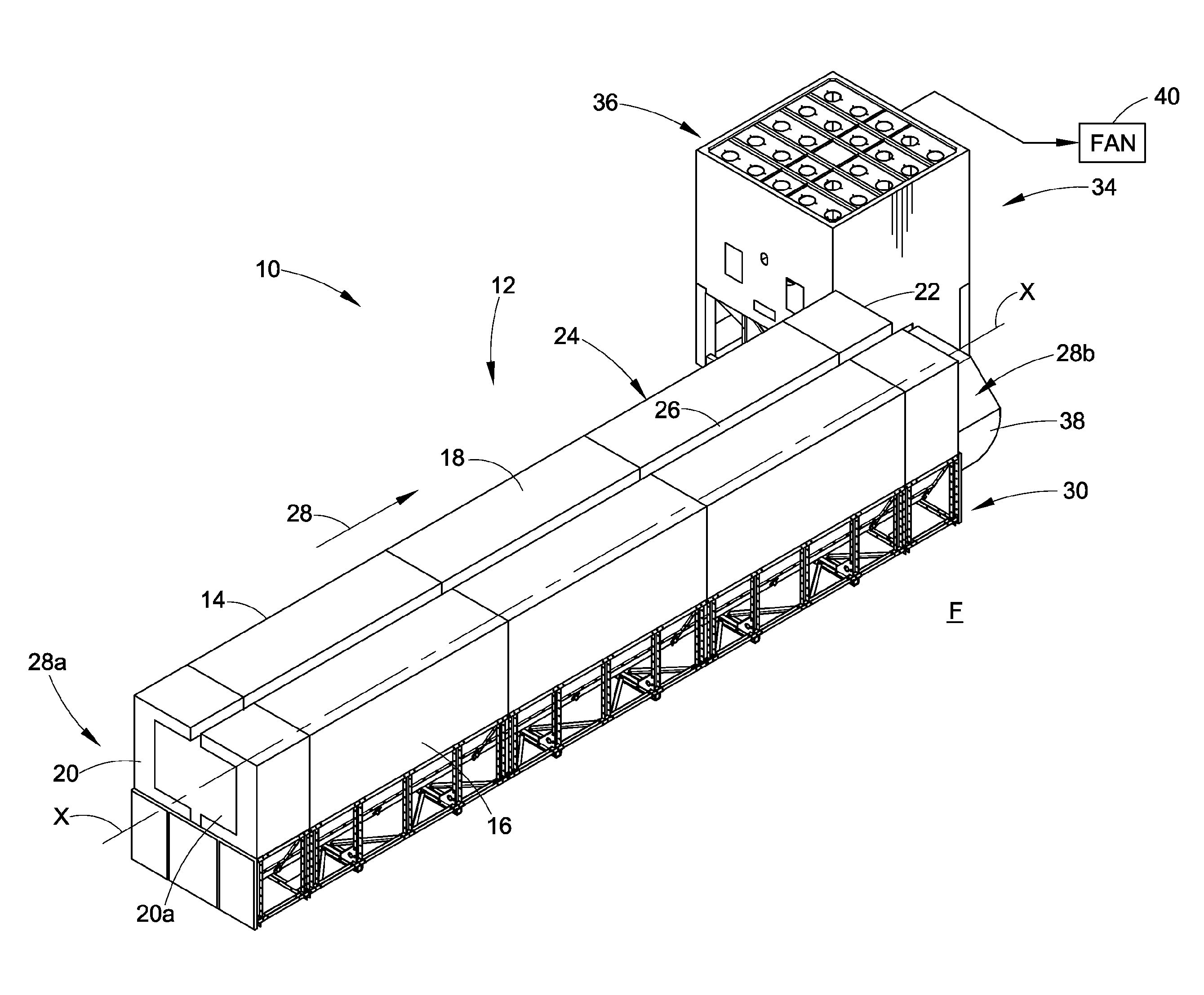
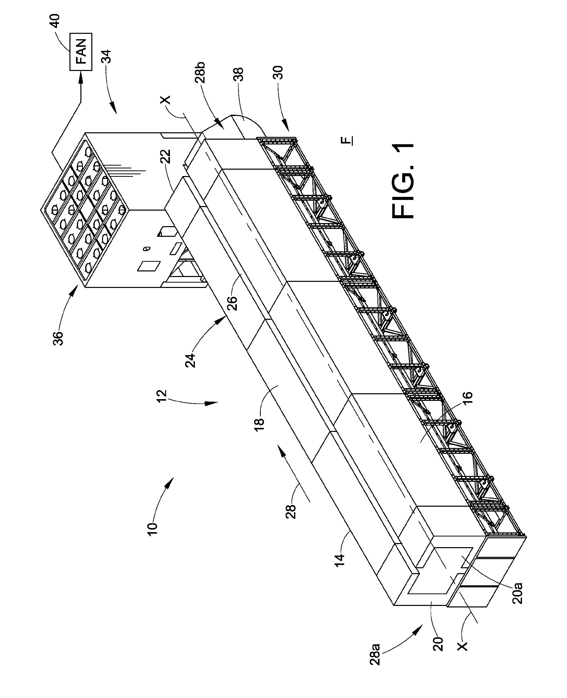
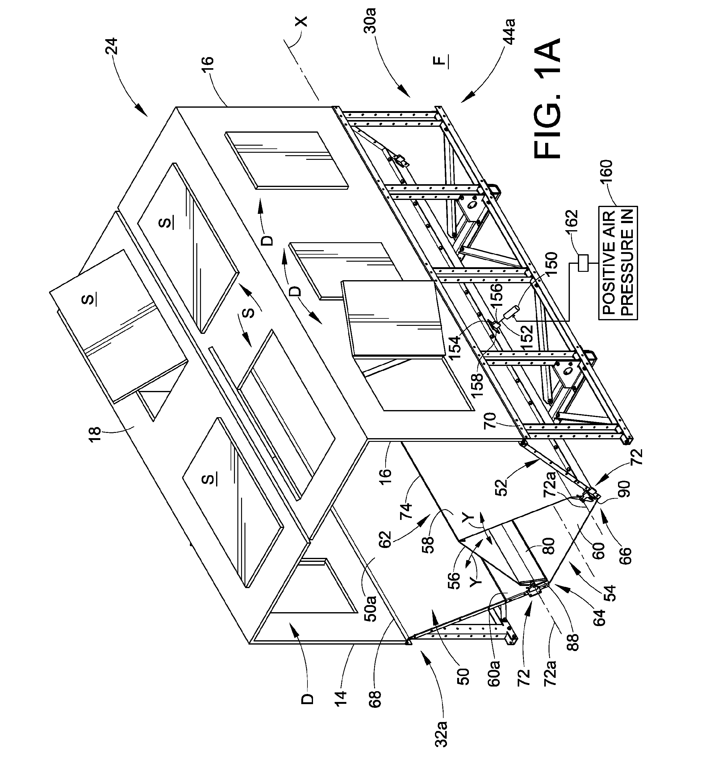
[0020]While the exemplary embodiments are presented in the context of a porcelain enamel or other glass type powder application system, the embodiments and the inventions are not limited necessarily to that exemplary material. The inventions may be used in other particulate coating material application apparatus including those that apply non-glass powder coating materials. The exemplary embodiments also illustrate use of the inventions with an exemplary spray booth configuration and an exemplary extraction suction arrangement, however, the inventions may be used with many different spray booth designs and configurations as well as many different extraction suction arrangements.

[0021]While various aspects and features of the inventions are described and illustrated herein as embodied in combination and sub-combinations in the exemplary embodiments, these various aspects may be realized in many alternative embodiments, either individually or in various alternative combinations and su...


PUM

PropertyMeasurementUnit
angleaaaaaaaaaa
angleaaaaaaaaaa
lengthaaaaaaaaaa

Abstract

Overspray collection apparatus comprises an extraction duct (54) between two sloped floors (50, 52) with unobstructed inlet slots (88, 90) on either side thereof. The extraction duct (54) comprises two moveable panels (56, 58) pivotally mounted to the sloped floors (50, 52). Each moveable panel (56, 58) pivots about an axis that is offset from a lower portion of the moveable panel and a lower portion of the sloped floor. In another embodiment, the pivotal mount comprises an offset hinge. The overspray extraction duct (54) comprises a duct floor (60) and an air diffuser assembly (100) that extends at least partially across the duct floor. The air diffuser assembly (100) receives pressurized air and directs pressurized air into the extraction duct (54), whereby the pressurized air may be pulsed. The overspray extraction duct (54) comprises a suction hood (62) that includes moveable panels (56, 58). Optional actuators may apply a force impulse to one or more of the moveable panels (56, 58), and/or to open and close the suction hood (62) automatically.

Description

RELATED APPLICATION[0001]The present application claims the benefit of pending U.S. Provisional patent application Ser. No. 61 / 595,297 filed on Feb. 6, 2012 for POWDER SPRAY BOOTH WITH IMPROVED OVERSPRAY COLLECTION, the entire disclosure of which is fully incorporated herein by reference.TECHNICAL FIELD OF THE DISCLOSURE[0002]The inventions relate generally to material application apparatus such as may be used, for example, to spray heavy coating material like glass. More particularly, the inventions relate to an overspray collection apparatus for removing overspray coating material from a spray containment booth.BACKGROUND OF THE DISCLOSURE[0003]A material application apparatus is regularly used for applying coating material to an object, part or other work piece or surface. A material application apparatus often includes a material application device, also referred to as a spray gun. Material application apparatus are often used to apply powder coating material and liquid coating ...

Claims


Application Information

Patent Timeline
Patent Type & Authority Applications(United States)
IPC IPC(8): B05B15/12
CPCB05B15/1259B05B15/1203B05B15/1214B05B14/44B05B16/40B05B14/10Y02P70/10
Inventor SHUTIC, JEFFREY R.SCHNEIDER, ROBERT D.DAILIDAS, JEFFERY EDWARD
Owner NORDSON CORP
Why Eureka
Try Eureka