Modularized system and method for urea production using a bio-mass feedstock

a bio-mass feedstock and module technology, applied in the direction of biofuels, waste based fuels, fuels, etc., can solve the problems of not being able to directly use to produce higher-order chemicals such as urea, the prior art requires large production units or large-scale plants, and the gasification of bio-mass to produce urea is yet untapped. , to achieve the effect of small footprint, cost-effectiveness and small scal

Inactive Publication Date: 2013-12-31
TRIMEC BIOGAS TECH LTD
View PDF11 Cites 4 Cited by
  • Summary
  • Abstract
  • Description
  • Claims
  • Application Information

AI Technical Summary

Benefits of technology

[0006]The bio-mass feedstock, which preferably has a moisture content of less than 15% by weight, may include a single bio-mass material having different processing characteristics or two or more bio-mass materials having a different processing characteristic such as density or calorific burn value. The pelletizing step pelletizes the cleaned bio-mass feedstock and provides pellets having substantially the same processing characteristics. Similarly, pellets produced from one type or quality of bio-mass feedstock may be combined and blended with pellets produced from another type or quality of bio-mass feedstock to produce a blend of the two pellet streams whose processing characteristics can be adjusted to maintain a consistency in temperature and burn quality for improved or optimal gasification.
[0007]The gasifying step preferably includes the sub-step of pulverizing the pellets to a fine particle size of about 1 mm. This fine particle size provides for a more efficient burn and a higher conversion rate of the bio-mass to gasified bio-mass (syngas). To further improve the efficiency and conversion performance of the gasifier, the gasifying step may also include the sub-step of injecting an organic oil into the input bio-mass feed stream or mist. The feed rate to the gasifier may be controlled so that the burn temperature of the gasifier, which may be in a range of 600° to 850° C., does not vary by more than ±25° C. By controlling the quality of the incoming bio-mass, pulverizing the bio-mass to a fine particle size, and regulating the feed rate in response to critical process parameters, the gasifier is effective for a conversion efficiency of about 98% or more.
[0009]The system and method according to this invention allows for small scale, cost effective conversion of bio-mass to higher order chemicals such as urea. For example, the equipment associated with each of the various process steps may be skid mounted or contained within the footprint of a standard 48-foot flatbed trailer. The modules may be interconnected at a single site or the cleaning module, pelletizing module, and gasifying module (and each module's associated processing steps) may each occur at a different geographical location. Modularity also allows the system to travel to the site of a bio-mass source, such as a farming community located in a remote rural area, where the method can be practiced on site.
[0010]An object of this invention is to provide a urea production plant that has a smaller footprint than conventional designs, is modular in construction, and can be easily transported, assembled for use, updated, modified, disassembled after use, and re-used. Another object of this invention is to provide a cost effective, low volume production plant. Another object of this invention is to provide a plant that can accommodate a bio-mass feedstock that is typically found in most rural areas—that is, of varying types, sizes, and process characteristics—and yet still achieve a high level of performance in converting this non-homogeneous bio-mass feedstock to a syngas useful in producing other products. Yet another object of this invention is to provide a bio-mass feedstock that is easily handled and provides increased density, reduced storage requirements, increased storage longevity, and reduced fire hazard potential. A further object of this invention is to provide a much cleaner and more uniform bio-mass feedstock to the gasification process than current processes provide. It is yet another object of this invention to provide a bio-mass feedstock that burns more evenly and reduces the production of by-products such as tar. Another object of this invention is to provide a clean syngas to the urea / ammonia conversion units. Still yet another object of this invention is to provide a bypass recycling loop system run at very high pressures to achieve almost a 100% conversion rate. A final object of this invention is to provide a process that simultaneously addresses all six of the technical barriers to the use of bio-mass to produce higher order chemicals such as urea.

Problems solved by technology

Although the conversion of biomass and biomass waste streams via the process of bio-gasification (syngas) to produce usable products has been accomplished to varying degrees of effectiveness and efficiency in the past, the gasification of bio-mass to produce urea is yet untapped.
Because this syngas is of low quality, it cannot be directly used to produce higher order chemicals such as urea.
In addition, the prior art requires large production units or large-scale plants.
Because of the size of the plants, the plants tend to be located far away from all of the ready and available sources of bio-mass feedstock, thereby increasing transportation costs or—in the case of remote rural or geographically challenging areas—making it extremely difficult if not economically infeasible to locate a plant or transport the bio-mass to the plant.
This bio-mass feedstock, which tends to be stored in fields prior to it being transported to the plant and processed, is usually dirty, of low storage density, and difficult to handle (see technical barrier 1).
This variation makes it difficult for plants to control, much less optimize, the conversion process and maintain a high level of conversion efficiency (see technical barriers 2 & 4-6 above).

Method used


Image

  • Modularized system and method for urea production using a bio-mass feedstock
  • Modularized system and method for urea production using a bio-mass feedstock
  • Modularized system and method for urea production using a bio-mass feedstock

Examples


Embodiment Construction

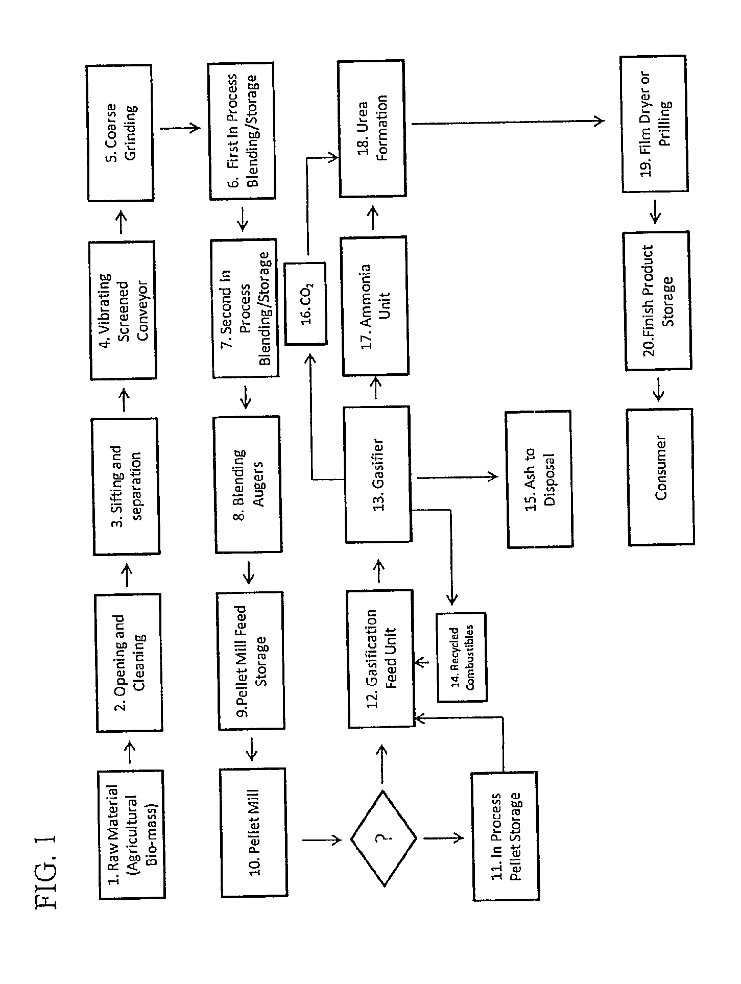
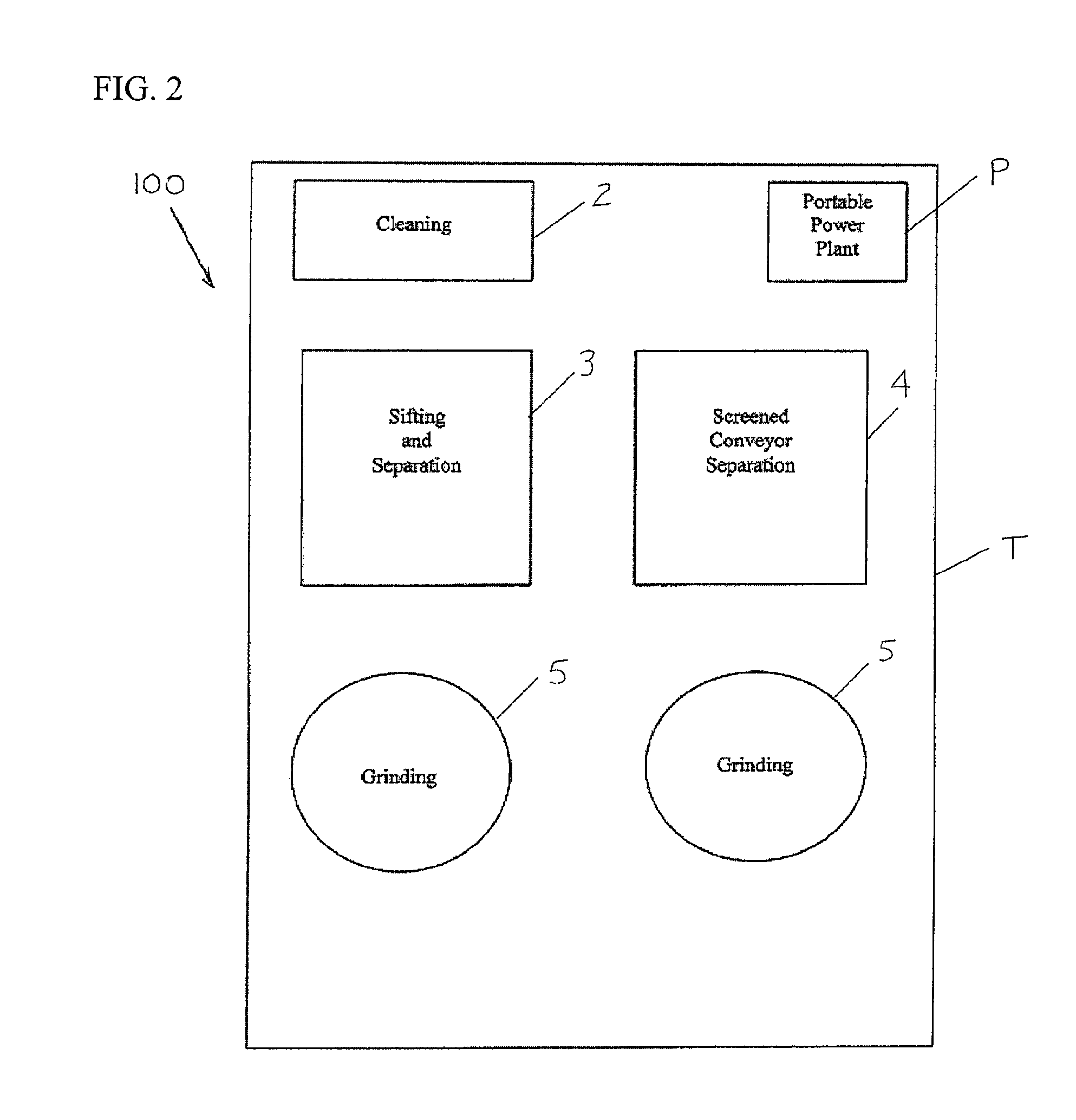
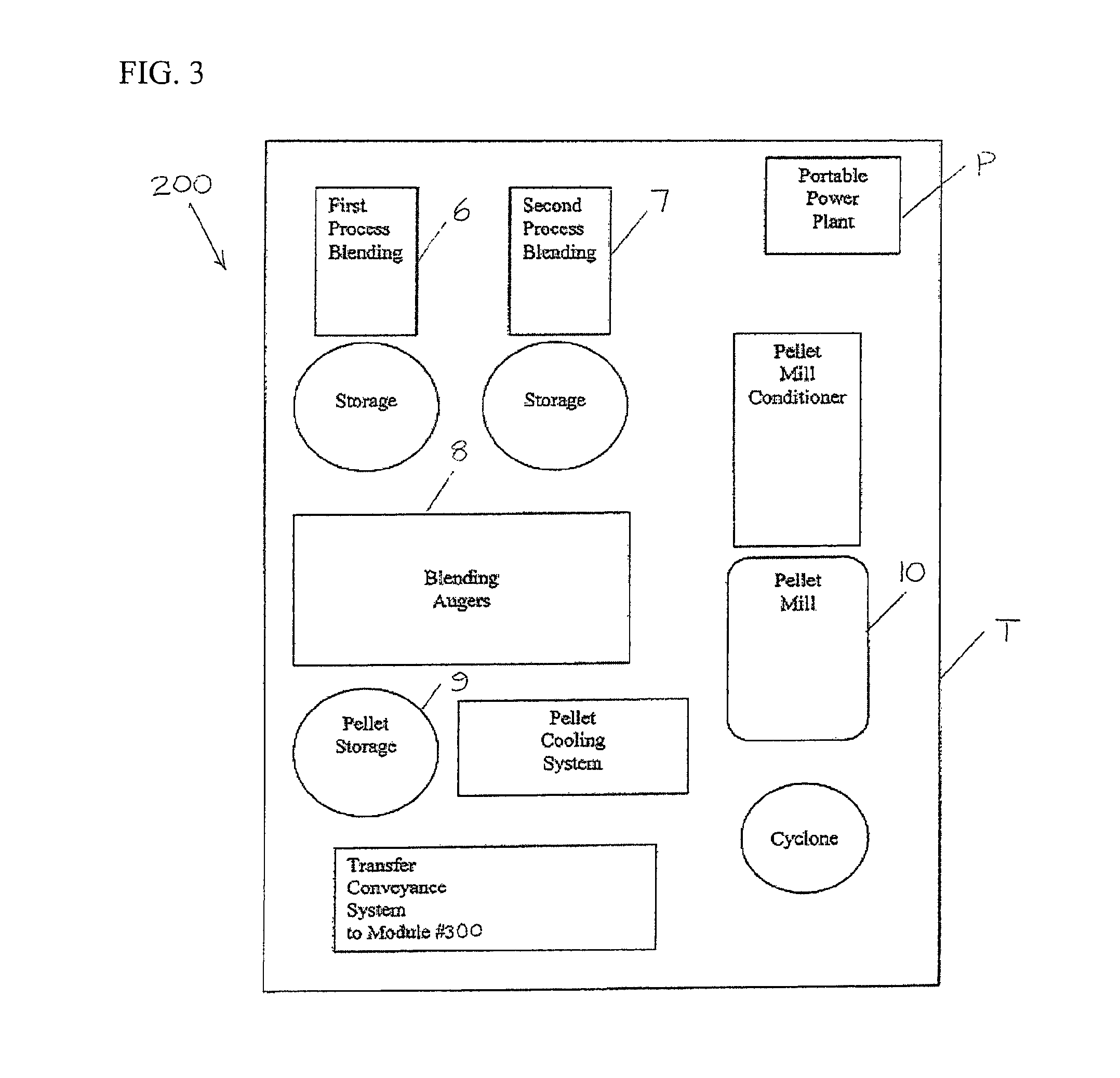
[0020]All six technical barriers listed in the Background of the Invention section are addressed in the following technical description for the conversion of biomass via the process of gasification to produce urea. The process—which is designed for cost effective low volume production (e.g. feed rates of 1 to 5 tons per hour) and modularized for improved process control and portability—provides a clean and consistent bio-mass feedstock to the gasifier. An on-demand organic oil injector is used to supplement the bio-mass mist in the gasification unit to maintain a constant, low fluctuating burn of the bio-mass. The gasification process also has a feed control system that serves as a bio-mass feed regulator. The gasified bio-mass (syngas) is then cleaned by running the syngas through a set of cyclones (gas cleaning system-scrubbers) before introducing the syngas to the ammonia / urea formation units.

[0021]Unlike the prior art systems, the process includes a bypass loop recycle system at...


PUM

PropertyMeasurementUnit
particle sizeaaaaaaaaaa
temperatureaaaaaaaaaa
pressureaaaaaaaaaa

Abstract

A modular system and method for producing urea from bio-mass includes cleaning a bio-mass feedstock to remove substantially all non-organic matter; blending the cleaned bio-mass to obtain a substantially homogeneous blend; pelletizing the blended bio-mass; and gasifying the pellets in a gasifier. The bio-mass feedstock may include bio-mass materials having different processing characteristics. The gasifying step preferably includes pulverizing the pellets to a fine particle size, injecting an organic oil into the input biomass mist when needed, and controlling the feed rate to maintain a substantially constant burn temperature. The resultant syngas stream is cleaned and compressed to a high pressure of about 6,000 to 7,000 psi. The resultant ammonia stream is processed in a bypass recycling loop system at 30% conversion rate at a high pressure of about 6,000 to 7,000 psi.

Description

CROSS-REFERENCE TO RELATED APPLICATIONS[0001]This application is the United States National Phase of PCT Patent Application No. US2009 / 053547 filed on 12 Aug. 2009, which was published in English on 18 Feb. 2010 under Publication No. WO 2010 / 019662 A1, which claims priority to U.S. Provisional Patent Application Nos. 61 / 088,253 and 61 / 088,178 both filed 12 Aug. 2008, which are incorporated herein by reference.BACKGROUND OF THE INVENTION[0002]The present invention relates generally to the conversion of bio-mass and bio-mass waste streams via the process of bio-gasification and, more specifically, to the conversion of bio-mass and bio-mass waste streams to produce higher order chemicals such as urea.[0003]Although the conversion of biomass and biomass waste streams via the process of bio-gasification (syngas) to produce usable products has been accomplished to varying degrees of effectiveness and efficiency in the past, the gasification of bio-mass to produce urea is yet untapped. The...

Claims


Application Information

Patent Timeline
Patent Type & Authority Patents(United States)
IPC IPC(8): C07C273/00
CPCC07C273/04C10J2300/092C10L5/363C10J2300/1668C10J2300/0906Y02E50/30C10J2300/1693C10L5/44Y02E50/10C10J2300/0903Y02P20/145
Inventor COLLINS, TERRY R.SIMONTON, JAMES L.BERUVIDES, MARIO G.LOZADA, JESSIE
Owner TRIMEC BIOGAS TECH LTD
Why Eureka
Try Eureka