Wing adjusting mechanism

a technology of adjusting mechanism and wing, which is applied in the field of aircraft, can solve the problems of increasing the weight and error rate of the adjustment mechanic, and the disadvantage of the propeller in the travel flight of the aircraft,

Inactive Publication Date: 2015-01-29
REITER JOHANNES
View PDF12 Cites 27 Cited by
  • Summary
  • Abstract
  • Description
  • Claims
  • Application Information

AI Technical Summary

Benefits of technology

[0006]It may be an object of the present inve...

Problems solved by technology

Propellers may have the disadvantage in travel flight of an aircraft due to a high drag.
In order to control and to drive such a tilting of the wings, complex an...

Method used


Image

  • Wing adjusting mechanism
  • Wing adjusting mechanism
  • Wing adjusting mechanism

Examples


Embodiment Construction

[0070]The illustration in the drawing is schematically. It is noted that in different figures, similar or identical elements are provided with the same reference signs.

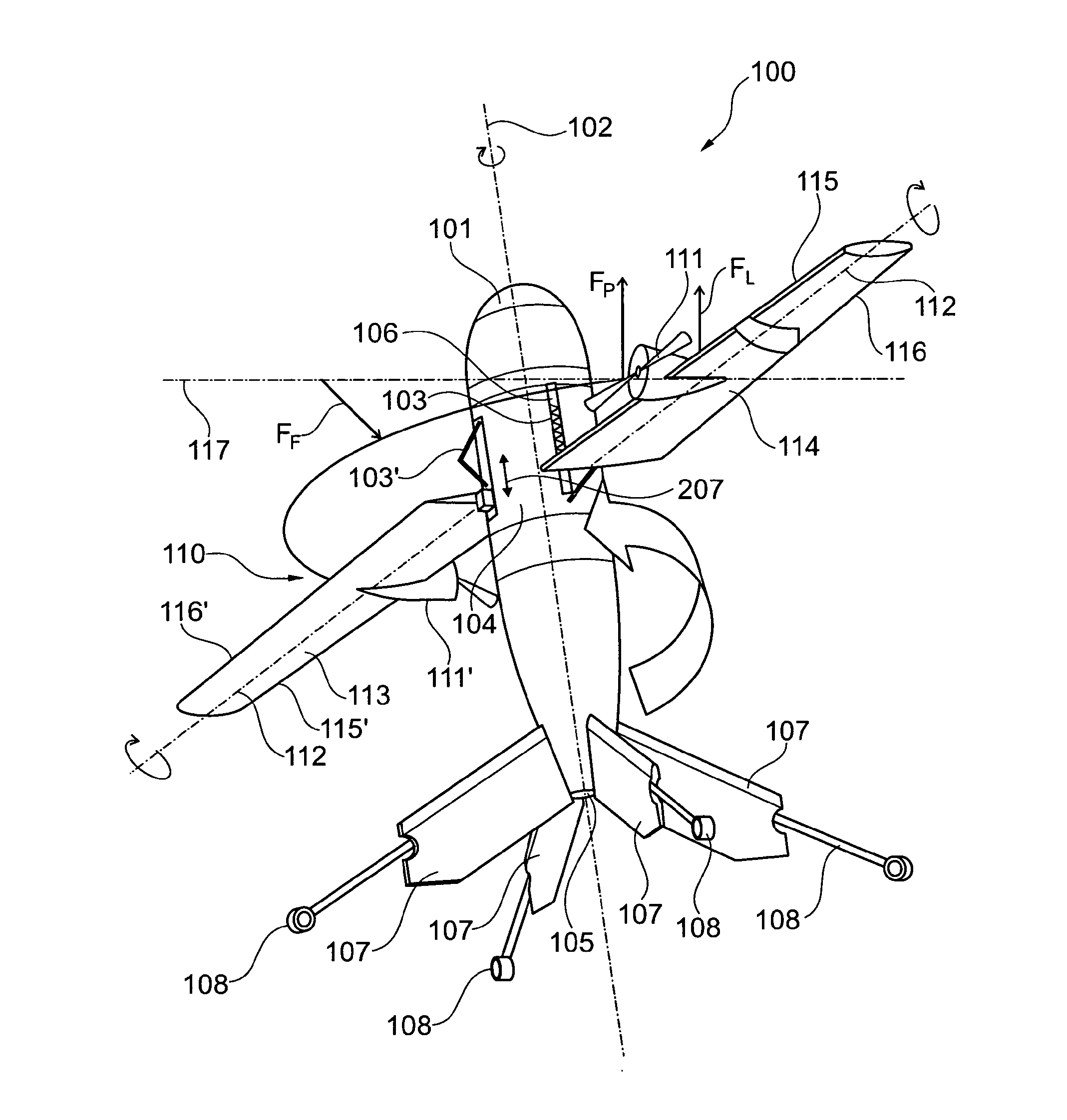
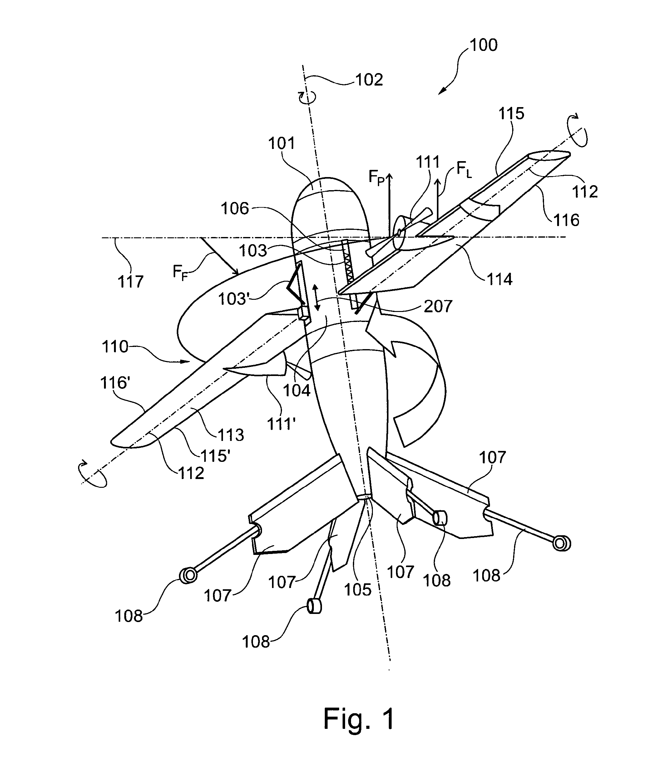
[0071]FIG. 1 shows an exemplary embodiment of an aircraft 100 for vertical take-off and landing according to an exemplary embodiment of the present invention. The aircraft 100 comprises a fuselage 101, a wing arrangement 110 which comprises at least one propulsion unit 111 and an adjusting mechanism.

[0072]The propulsion unit 111 comprises a rotating mass (e.g. a propeller or rotating blades of a jet engine) which is rotatable around a rotary axis 117. The wing arrangement 110 is mounted to the fuselage 101 such that the wing arrangement 110 is tiltable around a longitudinal wing axis 112 of the wing arrangement 110. Furthermore, the wing arrangement 110 is mounted to the fuselage 101 such that the wing arrangement 110 is rotatable with respect to the fuselage 101 around a further rotary axis 102 (e.g. a longitudinal f...


PUM


Abstract

The present invention relates to a device for generating aerodynamic lift and in particular an aircraft (100) for vertical take-off and landing. A wing arrangement (110) comprises at least one propulsion unit (111), wherein the propulsion unit (111) comprises a rotating mass which is rotatable around a rotary axis (117). The wing arrangement (110) is mounted to a fuselage (101) such that the wing arrangement (110) is tiltable around a longitudinal wing axis (112) of the wing arrangement (110) and such that the wing arrangement (110) is rotatable with respect to the fuselage (101) around a further rotary axis that differs to the longitudinal wing axis (112). An adjusting mechanism adjusts a tilting angle of the wing arrangement (110) around the longitudinal wing axis (112) under influence of a precession force (Fp) which forces the wing arrangement (110) to tilt around the longitudinal wing axis (112).

Description

FIELD OF THE INVENTION[0001]The present invention relates to an aircraft for vertical take-off and landing and to a method for operating an aircraft for vertical take-off and landing.BACKGROUND OF THE INVENTION[0002]It is an aim to have aircraft that are able to start and land without a runaway for example. Hence, in the past several developments for so called Vertical Take-Off and Landing aircraft (VTOL) have been done. Conventional VTOL-Aircraft need a vertical thrust for generating the vertical lift. Extreme thrust for vertical take-off may be produced by big propellers or jet engines. Propellers may have the disadvantage in travel flight of an aircraft due to a high drag.[0003]An efficient solution for a hover flight capable aircraft is performed by helicopters, using e.g. a big wing area. In a known system, an aircraft comprises an engine for vertical lifting the aircraft (e.g. a propeller) and e.g. a further engine for generating the acceleration of the aircraft in a travel mo...

Claims


Application Information

Patent Timeline
IPC IPC(8): B64C27/00B64C3/38B64C29/00
CPCB64C27/00B64C27/001B64C3/385B64C29/00B64C27/16B64C27/18B64C29/0075B64C29/02B64C29/0033B64U30/12B64U70/80B64U50/13B64U10/25B64U60/40B64U50/12B64C39/008B64C39/024B64U30/10B64U30/20B64C3/38
Inventor REITER, JOHANNES
Owner REITER JOHANNES
Why Eureka
Try Eureka