Optical Apparatus And Method

Inactive Publication Date: 2015-01-29
KNOWLES ELECTRONICS INC +1
View PDF0 Cites 26 Cited by
  • Summary
  • Abstract
  • Description
  • Claims
  • Application Information

AI Technical Summary

Problems solved by technology

Physical limitations that characterize the application setting do not always readily accommodate such movement, however.
Lack of available space, friction, slip-stick, or issues with establishing initial lens alignment, or lens

Method used


Image

  • Optical Apparatus And Method
  • Optical Apparatus And Method
  • Optical Apparatus And Method

Examples


Embodiment Construction

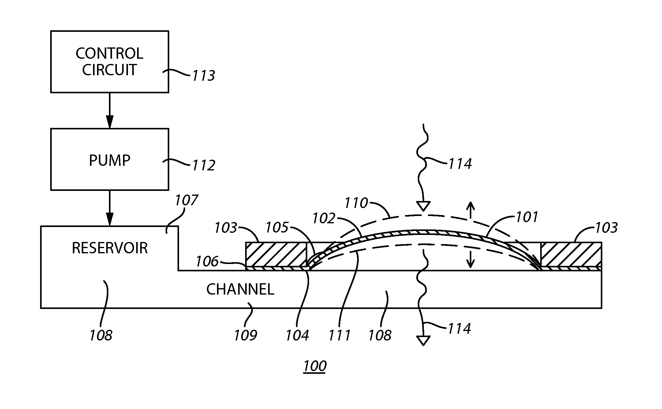
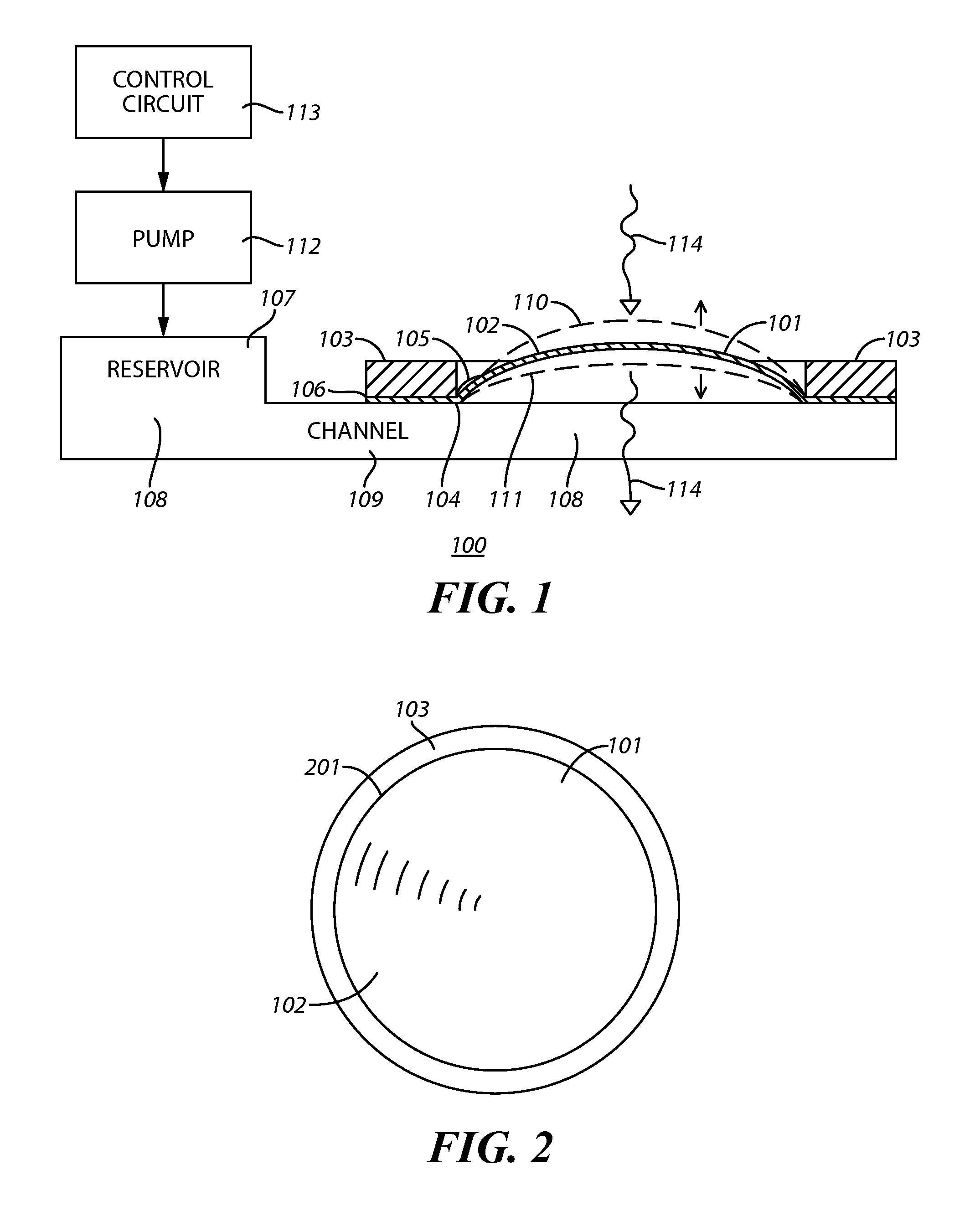
[0061]One aspect to the functioning of imaging optics is that the lenses have a well-defined shape and that the lens is in the correct position and that this is maintained over the life of the product. The shape of a deformable optical lens is a function of the membranes material properties, how the membrane is mounted, how the system is treated in processing the parts to the final state and of course the pressure being applied to it. Modifying these processes as described herein can allow a user to obtain a desired shape and have this shape maintained over the life of the product.

[0062]The optical function of deformable optical lens system is determined at least in part by the shape of the flexible membrane at the air membrane interface, the properties of the optical fluid, the shape and optical properties of the fixed solid lens serving to contain the fluid. The approaches to control the deformable optical lens membrane / air shape described herein then further define this shape wit...


PUM

PropertyMeasurementUnit
Lengthaaaaaaaaaa
Fractionaaaaaaaaaa
Angleaaaaaaaaaa

Abstract

A deformable optical lens with a lens membrane having an optically active portion that is configured to be shaped over an air-membrane interface according to a spherical cap and Zernike polynomials is provided. The spherical cap and the Zernike polynomials comprise a Zernike[4,0], (Noll[11]) polynomial and are sufficient to model the deformable optical lens to within approximately 2 micrometers.

Description

CROSS REFERENCE TO RELATED APPLICATION[0001]This application claims benefit under 35 U.S.C. §119 (e) to U.S. Provisional Application No. 61 / 858,706 entitled “Method and Apparatus Pertaining to a Deformable Optical Lens,” filed Jul. 26, 2013, the content of which is incorporated herein by reference in its entirety.TECHNICAL FIELD[0002]This application relates to optical lenses including optical systems having selectively deformable optical lenses.BACKGROUND OF THE INVENTION[0003]A lens is an optical device that transmits and refracts light to (typically) converge or diverge incoming light in a desired manner. Lenses are typically made of glass or transparent plastic. Many lenses are spherical lenses and hence have surfaces that are parts of the surfaces of spheres. Such surfaces can be convex (bulging outwards from the lens), concave (depressed into the lens), or planar (flat). Other lenses are aspheric lenses.[0004]Devices such as cameras (including digital cameras) typically utiliz...

Claims


Application Information

Patent Timeline
IPC IPC(8): G02B3/14G02B17/08G02B7/04F04B17/00H01L27/146H01L31/0232F04B17/03G02B3/12B29D11/00
CPCG02B3/14G02B3/12G02B17/08G02B7/04F04B17/003H01L27/14625H01L27/14629H01L31/02325F04B17/03B29D11/0073B29D11/00461F04B43/046G02B7/102G02B13/0045G02B15/177
Inventor KING, CHARLESGRAETZEL, CHAUNCEYDAVOINE, LAURENTMONTI, CHRISTOPHERSCHMIDHAEUSLER, THOMASBUEELER, MICHAELSALT, MARTINKUKALEVA, NATALIALIEBETRAUT, PETER
Owner KNOWLES ELECTRONICS INC
Why Eureka
Try Eureka