
Near-Field Optical Apparatus And Method Using Photodetector Array

a technology of optical apparatus and array, applied in the field of near-field optical apparatus and method using photodetector array, can solve the problems of slow imaging speed, stm, afm, and nsom, and can't substitute optical microscope for many applications, and achieve the effect of fast imaging speed

Inactive Publication Date: 2008-06-19
LI CHIAN CHIU
View PDF3 Cites 10 Cited by
  • Summary
  • Abstract
  • Description
  • Claims
  • Application Information

AI Technical Summary

Benefits of technology

[0012]c). to provide such a microscope which is of image type and has a fast imaging speed;

Problems solved by technology

Electron microscope, STM, and AFM however, can't substitute optical microscope for many applications, especially in biomedical fields because, they lack ability of chemical and molecular identification.
NSOM, on other hand, has its own drawbacks, which include slow imaging speed, operation complexity, and difficulties with soft sample, sample in solution, and dynamic observation.
The weakness of NSOM has hampered its usefulness and application ever since it was first made more than twenty years ago.

Method used


Image

  • Near-Field Optical Apparatus And Method Using Photodetector Array
  • Near-Field Optical Apparatus And Method Using Photodetector Array
  • Near-Field Optical Apparatus And Method Using Photodetector Array

Examples


Embodiment Construction

FIGS. 1-A to 1-D—Prior-Art

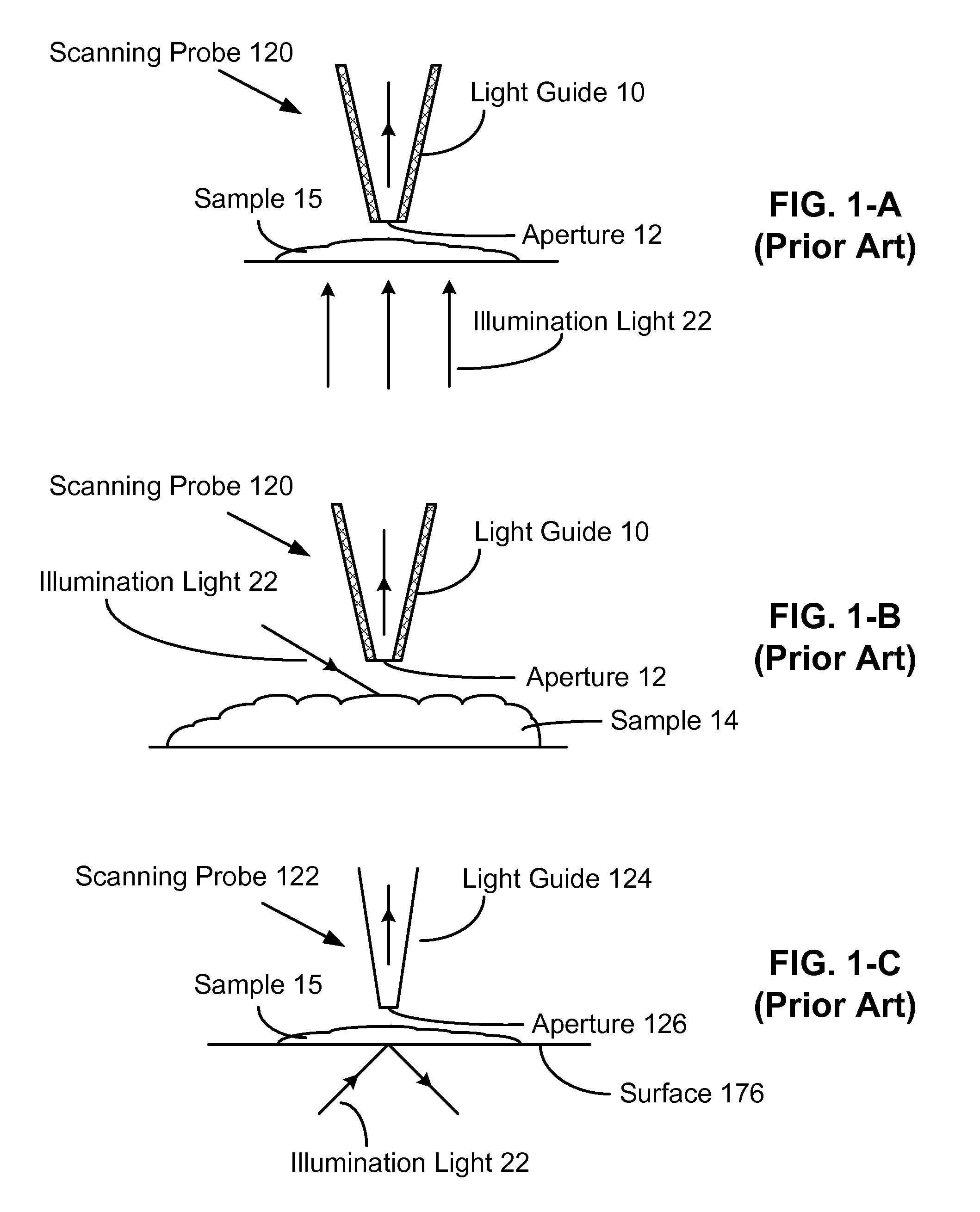
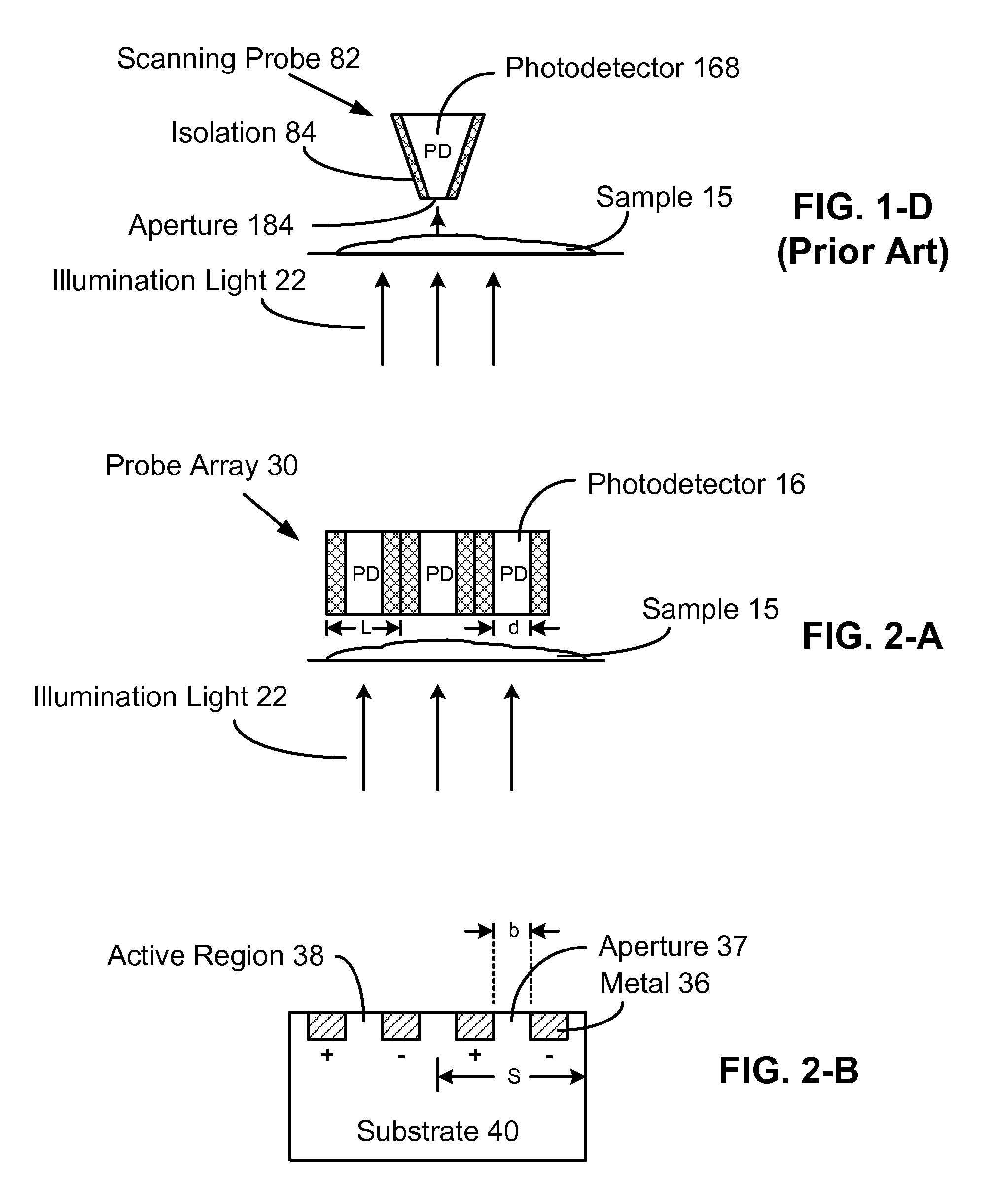
[0035]FIG. 1-A shows a prior-art NSOM of transmission-collection mode. A scanning probe 120 contains a tip-like light guide 10 which is coated with metal on its outside surface. A beam 22 as illumination light is transmitted to impinge onto a sample 15. An aperture 12 at the apex of light guide 10 collects light signals which emerge from the sample. The aperture has a subwavelength dimension and is positioned within subwavelength distance from sample 15 such that it receives near-field signals of the sample. To gain nanoscale resolution, the aperture dimensions and distance between the aperture and a sample are made to be in the deep subwavelength range, or nanoscale range. Signals collected through the aperture and light guide are sent to a detecting system. The light signals are then converted to electrical currents, amplified, and stored subsequently. Each time, one spot of the sample is measured. For a selected sample area, spots are scanned and data is...


PUM


Abstract

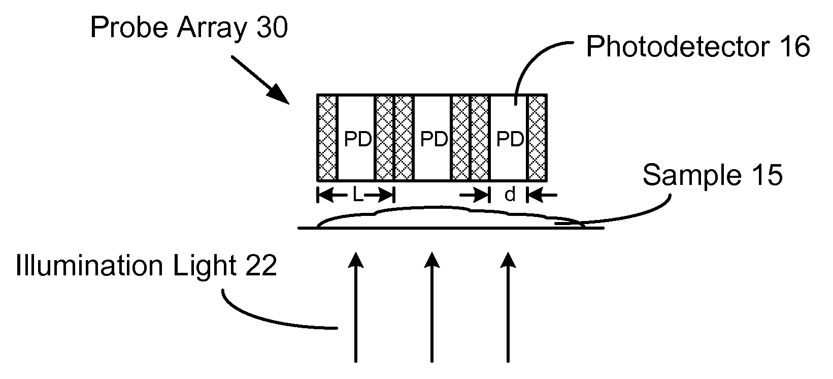
An imaging-type near-field optical microscope mainly comprises a light source and a photodetector array. The array functions as imaging array where each cell or photodetector has subwavelength dimensions. A sample under test is disposed in optical near field of the photodetectors, e.g., on surface of the array. As a result of subwavelength dimensions and near-field effect, resolution can break the diffraction limit and even reach nanoscale. The microscope has a fast speed, works with soft sample and sample in solution, and is capable of dynamic observations. In addition, the array surface doubles as a platform for molecule manipulation.

Description

CROSS REFERENCE TO RELATED APPLICATION[0001]This application claims the benefit under 35 U.S.C. Sec. 119 of provisional patent application Ser. No. 60 / 867,795, filed Nov. 30, 2006.FEDERALLY SPONSORED RESEARCH[0002]Not applicableSEQUENCE LISTING OR PROGRAM[0003]Not applicableBACKGROUND[0004]1. Field of Invention[0005]This invention relates to optical microscopy, and particularly to near-field optical microscopy.[0006]2. Description of Prior Art[0007]Optical microscope is a well-known and widely used instrument. Due to the diffraction limit, its maximum resolution which we are able to get is about 200 nanometers. To observe finer details, other microscopes had been developed, for example, electron microscope, scanning tunneling microscope (STM), and atomic force microscope (AFM), all with sub-nanometer resolution. Electron microscope, STM, and AFM however, can't substitute optical microscope for many applications, especially in biomedical fields because, they lack ability of chemical ...

Claims


Application Information

Patent Timeline
Patent Type & Authority Applications(United States)
IPC IPC(8): G01J3/447G01J3/28
CPCB82Y20/00B82Y35/00G01J1/0209G01Q70/06G01J3/0259G01J3/2803G01Q60/22G01J1/4228
Inventor LI, CHIAN CHIU
Owner LI CHIAN CHIU
Learn More