Isolated battery management systems and methods thereof

Active Publication Date: 2015-01-29
GENERAL ELECTRIC CO
View PDF5 Cites 2 Cited by
  • Summary
  • Abstract
  • Description
  • Claims
  • Application Information

AI Technical Summary

Benefits of technology

[0007]In an embodiment, a method is provided that includes at least the following steps: receiving a DC bus voltage from a power grid; reducing the DC bus voltage from a first voltage to an isolated second voltage; reducing the second voltage to at least one of an isolated third voltage or an isolated fourth voltage; reducing the second vol

Problems solved by technology

Battery management systems often have high-pot failures, signal noises

Method used


Image

  • Isolated battery management systems and methods thereof
  • Isolated battery management systems and methods thereof
  • Isolated battery management systems and methods thereof

Examples


Embodiment Construction

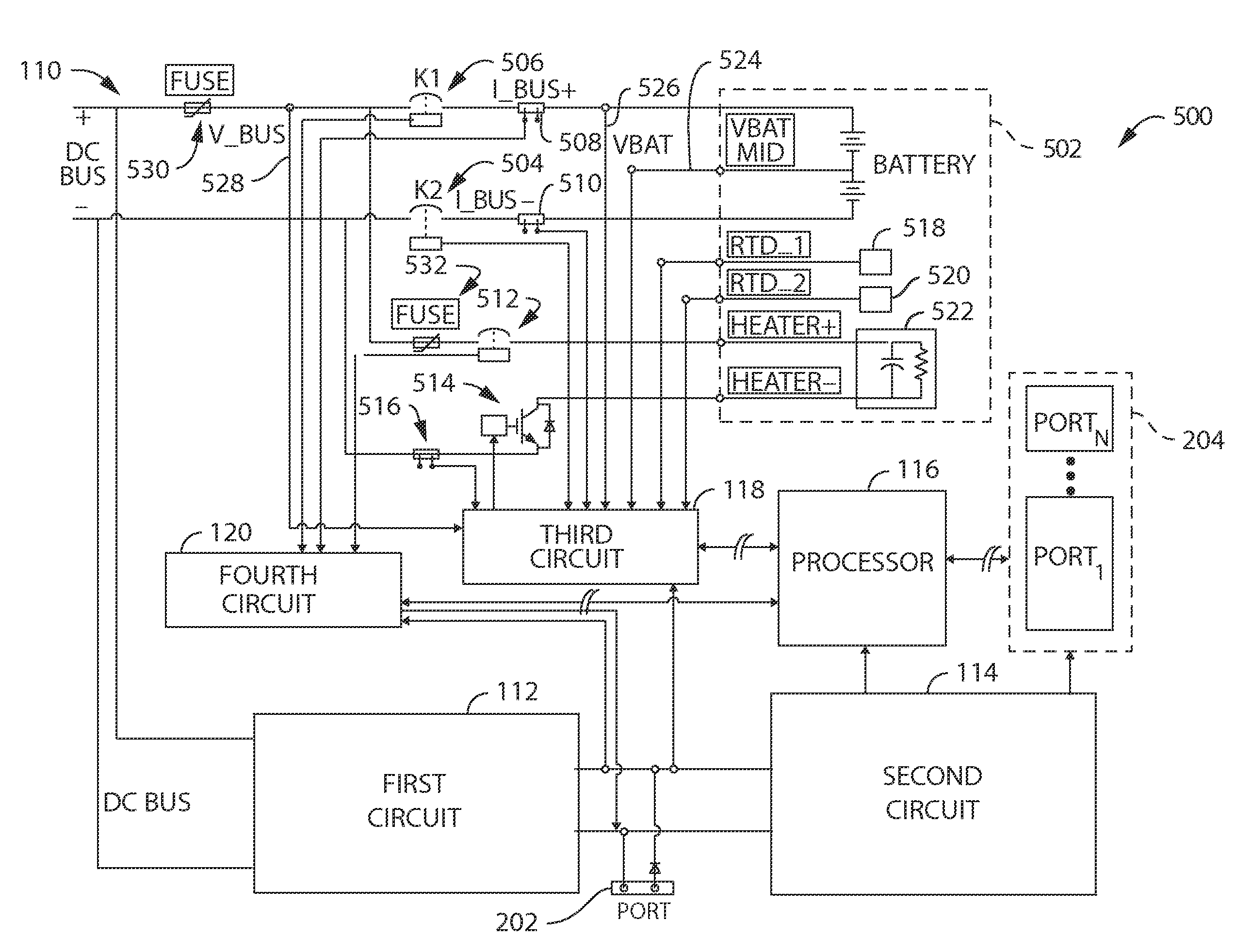
[0017]Conventionally, a battery management system used flayback power supply topology in which sensor circuits were not isolated from a processor. These conventional systems provided high voltage risks to other devices or interface circuits tied to the controller based on connectivity of high voltage to the controller. Moreover, conventional port(s) for programming, communicating, debugging, among others were also tied to high voltage which provided a touch hazard that could harm individuals operating with the port(s). Conventional battery management systems further include grounding interference issues with other equipment in inverter power systems. These conventional battery management systems included a grounding path that tied to a chassis and caused grounding fault protection tripping from inverter or other equipment in the battery management system. Additionally, hipot tests would provide a false positive due to grounding leakage current (e.g., current interference). Conventio...


PUM


Abstract

Systems and methods of the invention relate to circuitry that isolates low power circuitry of a battery management system. One or more circuits can be utilized with a battery management system to provide isolation of low power circuitry from at least one of a high voltage, noise interference from a battery, noise interference from a high voltage, sensor signals, control signals, among others. The circuitry further provides high voltage from a grid to be stepped-down to a voltage level usable by circuitry, port(s), and/or a processor.

Description

BACKGROUND[0001]1. Technical Field[0002]Embodiments of the subject matter disclosed herein relate to battery management circuitry designs.[0003]2. Discussion of Art[0004]Battery management systems can include various components, circuitry, hardware, and the like. Battery management systems often have high-pot failures, signal noises, sensor noises, inverter grounding interference, and voltage leakage. Conventional battery systems use a processor that uses signals comingled with noise or other interferences that can affect performance.[0005]It may be desirable to have a system and method that differs from those systems and methods that are currently available.BRIEF DESCRIPTION[0006]In an embodiment, a system is provided that includes a first circuit that is configured to convert a first voltage of a DC bus to a lower second voltage and isolate the second voltage from the first voltage. The system further includes at least one of a third circuit or a fourth circuit. The third circuit ...

Claims


Application Information

Patent Timeline
IPC IPC(8): H02J1/00
CPCH02J2001/008H02J1/00G06F1/26H02M3/335H02J1/082H02J1/10H02J7/02H02J2207/20H02J1/06H02J7/34
Inventor ZHU, HUIBINZHOU, HUA
Owner GENERAL ELECTRIC CO
Why Eureka
Try Eureka