
Eureka
For R&D, Eureka makes reading and utilizing patents & technical documents easy.
Eureka AIR
Designed for self-driven R&D workflows. Generate viable solutions, solve complex R&D challenges, empower your innovation with AI.

Eureka Materials
Designed for material experts only. Revolutionize your material R&D, from search, analyze, to developing new materials.

TechResearch
Generate reliable direction feasibility study reports for your R&D in just a few steps.

TechSeek
Discover and master advanced knowledge NOW. Basics, ideas, possibilities, all at once.

TechMind
As an expert in R&D Theories, TechMind can generates customized viable solutions instantly.

TechRisk
Analyze your overall solution with one click, know your potential R&D risks in advance.

TechMonitor
Get weekly tech updates, stay abreast of the latest tech innovations and key insights.
Straight tube light-emitting lamp
- Summary
- Abstract
- Description
- Claims
- Application Information
AI Technical Summary
Benefits of technology
Problems solved by technology
Method used
Image

Examples
embodiments
[0023]Embodiments of the present invention will be described below in detail with reference to the drawings.
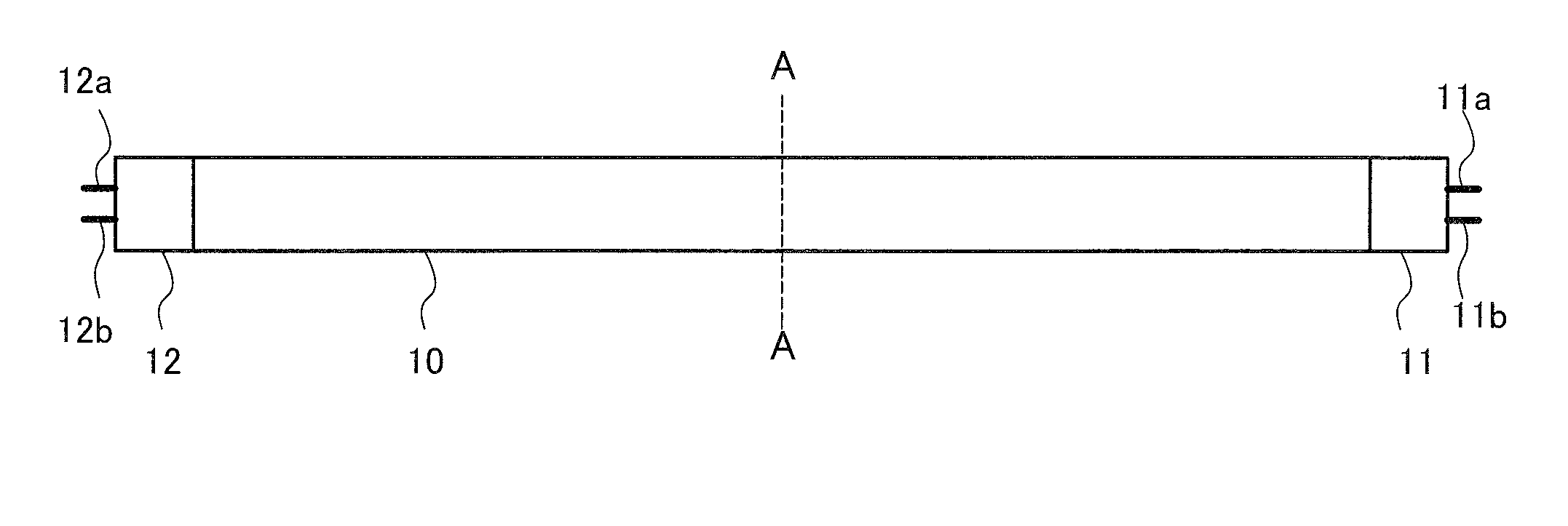
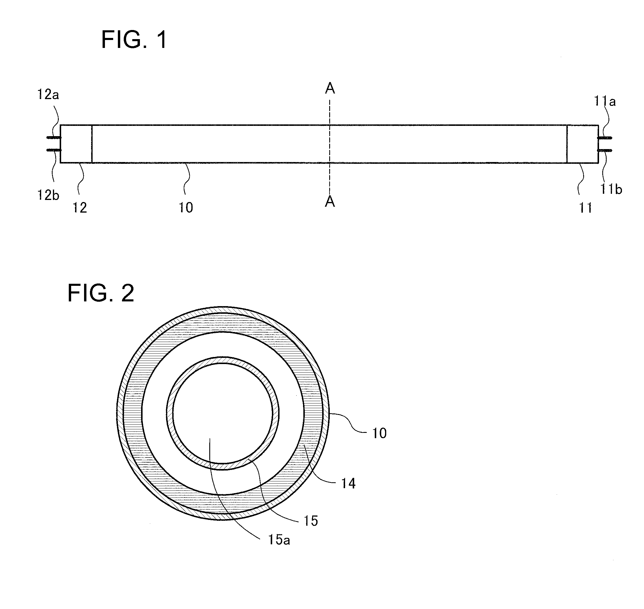
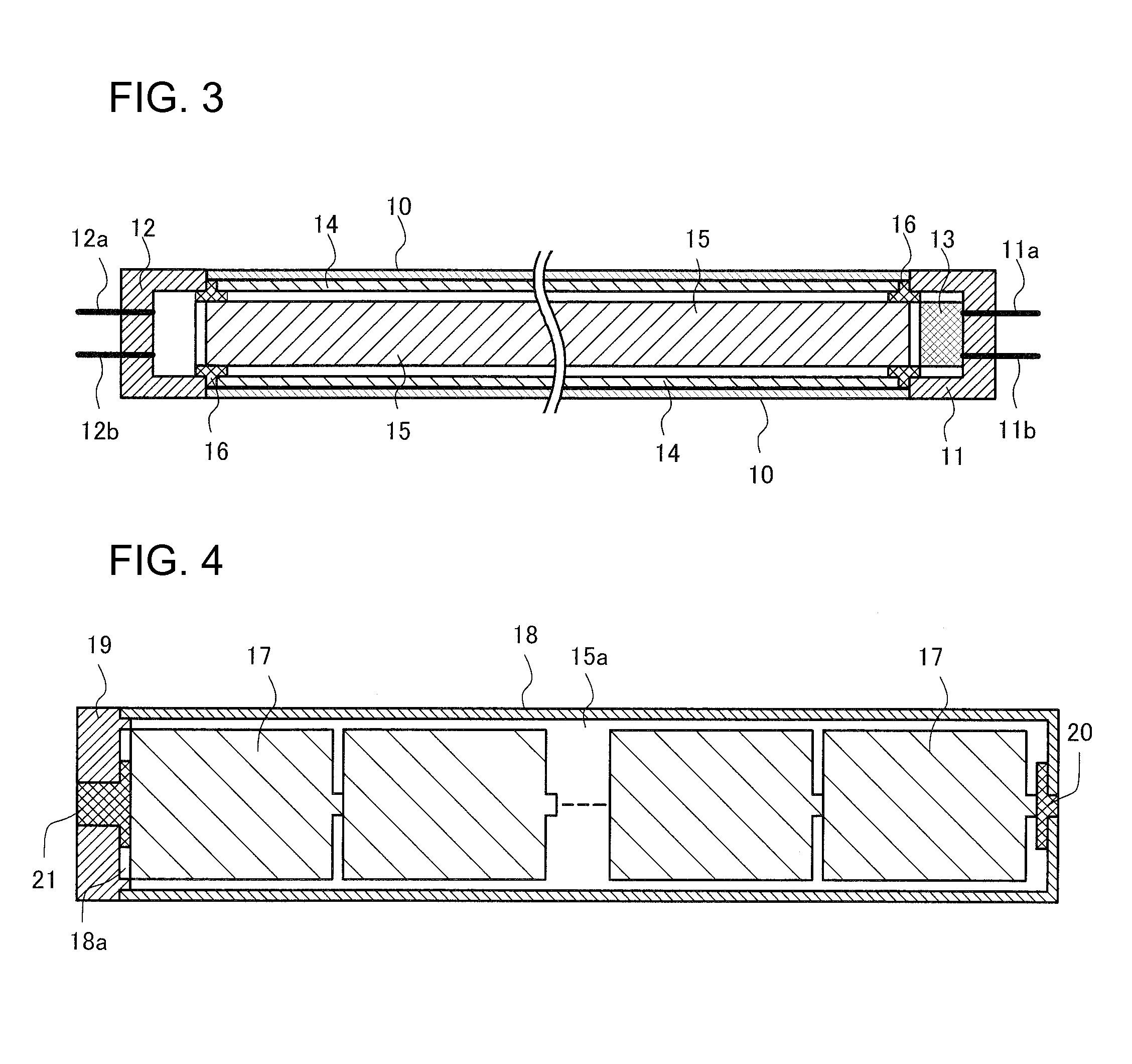
[0024]FIG. 1 illustrates an exterior of a straight tube light-emitting lamp according to the first embodiment of the present invention. FIG. 2 illustrates a transverse section of the straight tube light-emitting lamp in FIG. 1. FIG. 3 illustrates a longitudinal section of the straight tube light-emitting lamp in FIG. 1. As illustrated in FIG. 1, this straight tube light-emitting lamp includes: a cylindrical transparent glass tube (including semitransparent) 10 as a pipe-shaped transparent tube; and two bases 11 and 12. Other than a glass, the pipe-shaped transparent tube may be made of a resin such as acrylic. The tubular transparent glass tube 10 has openings at both ends thereof. The bases 11 and 12 are provided for the openings so as to cover the respective openings. The base 11 is fixed to the opening at one end of the cylindrical transparent glass tube 10 and the base 12 ...
PUM
 Abstract
Description
Claims
Application Information
 - R&D Engineer
- R&D Manager
- IP Professional
- Industry Leading Data Capabilities
- Powerful AI technology
- Patent DNA Extraction
Browse by: Latest US Patents, China's latest patents, Technical Efficacy Thesaurus, Application Domain, Technology Topic, Popular Technical Reports.
© 2024 PatSnap. All rights reserved.Legal|Privacy policy|Modern Slavery Act Transparency Statement|Sitemap|About US| Contact US: help@patsnap.com