
Ultra broadband networks and methods

a technology of ultra-wideband and broadband networks, applied in the field of ultra-wideband networks and methods, can solve the problems of prohibitively expensive and time-consuming approaches to achieve domestic universal coverage, and the inability to achieve the goal using current technology,

Inactive Publication Date: 2015-01-29
SLEMP DAVID A
View PDF0 Cites 6 Cited by
  • Summary
  • Abstract
  • Description
  • Claims
  • Application Information

AI Technical Summary

Benefits of technology

This patent aims to use existing aircraft traffic as a platform to transmit wireless communication data via E-band at high altitudes. The invention also aims to provide backhaul services for remote cellular network base stations and design commercial methods for implementing an ultra wide-band communications data network. The technical effects of this patent include improving wireless communication at high altitudes and eliminating the need for a high bandwidth backhaul data network.

Problems solved by technology

However, constraints on achieving this goal using current technology translate to decades of delay, if not rendering it completely impractical from a cost perspective, because the current system of cellular based communication systems requires continually expanding, upgrading, and maintaining a vast terrestrial network of short range transceiver base stations.
This approach will be prohibitively costly and time consuming to achieve domestic universal coverage.
An additional obstacle to universal coverage is the cost of providing backhaul.
However, many cellular base stations are located where telephone lines are not available.
However, transmission of data is limited geographically by the lack of universal availability of cellular base stations within the line of site of an end user's mobile wireless device.
Additionally, any number of obstructions, including hills, trees, buildings and mountains, exist between end user devices and base stations and can potentially disrupt the line of sight and therefore communication.
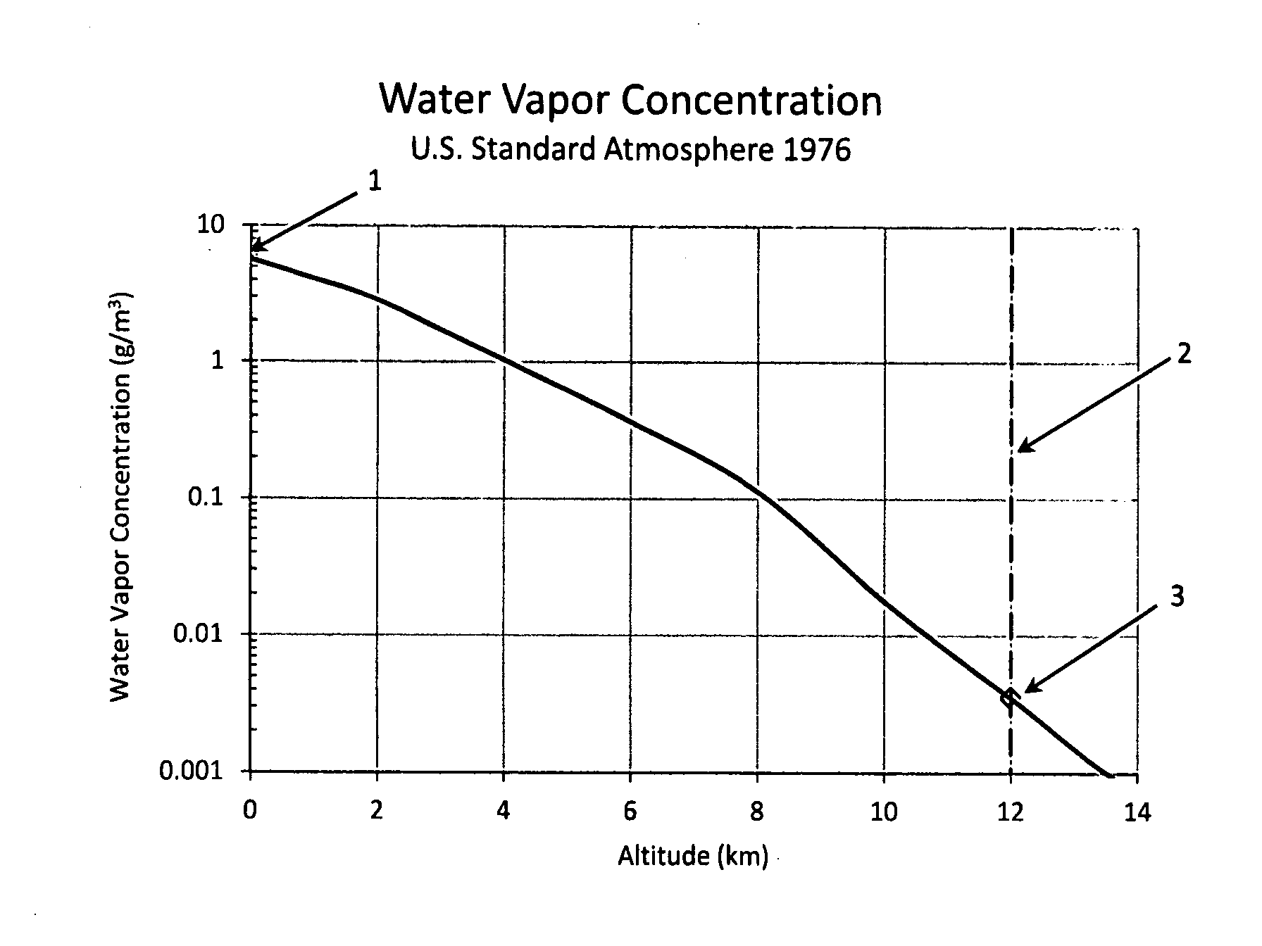
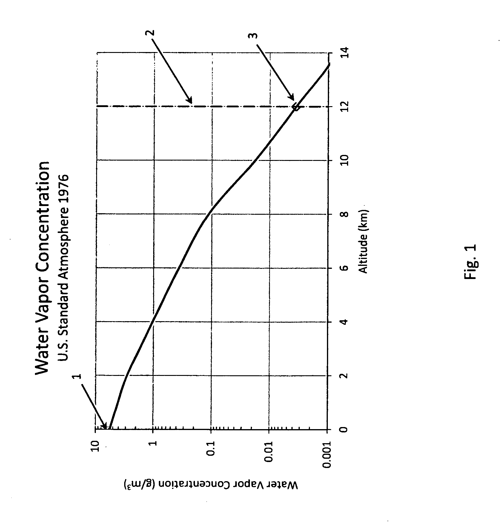
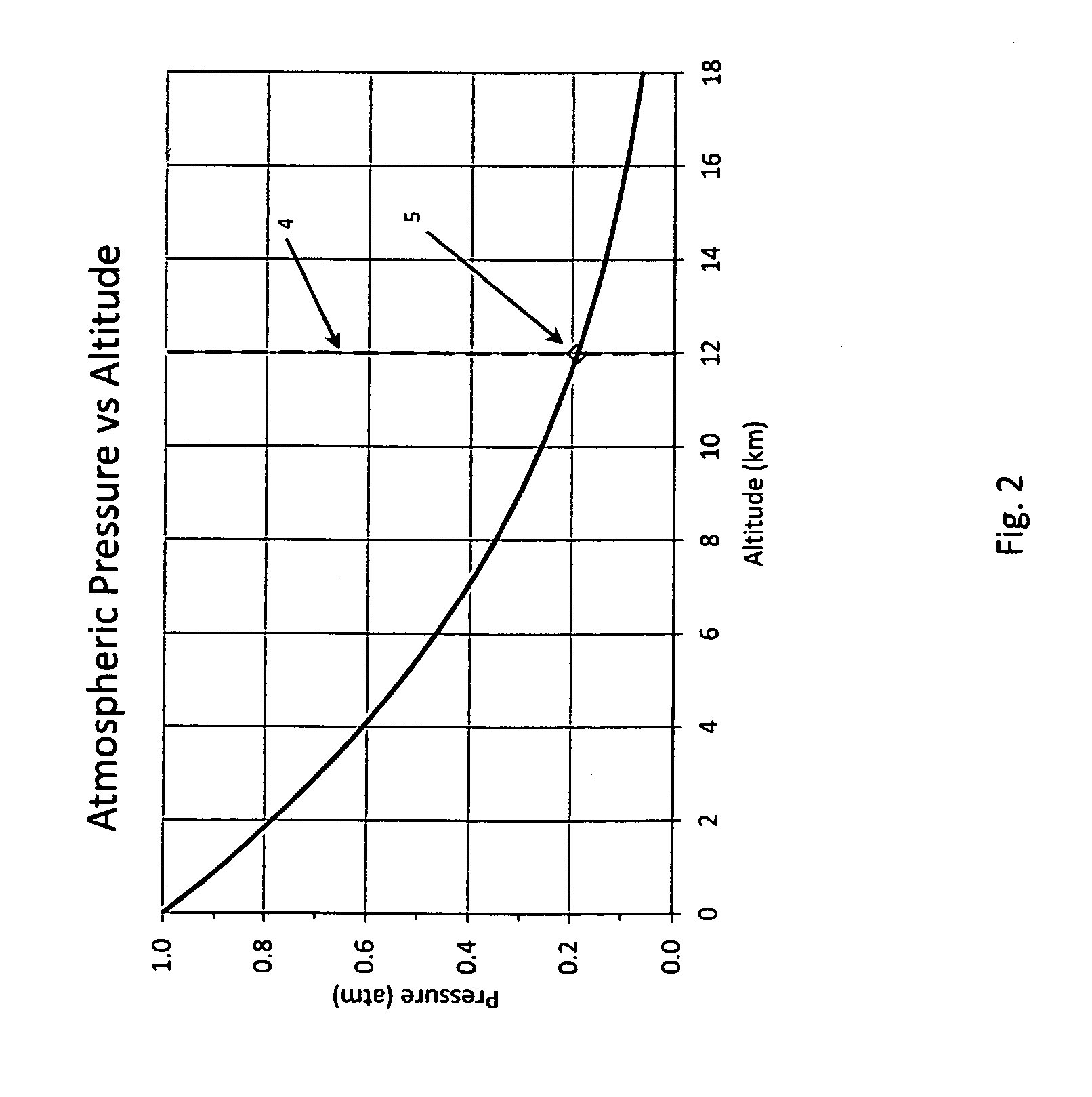
However, as it is used today, E-band is not well suited for communicating over very long distances.

Method used


Image

  • Ultra broadband networks and methods
  • Ultra broadband networks and methods
  • Ultra broadband networks and methods

Examples


Embodiment Construction

[0024]FIG. 4 illustrates an example of a simple communication path for voice or data between clients. In this example, a first client is using a first end user device, cellular telephone 8. The second end user is using a tablet 9. The communication path in FIG. 4 travels from cellular telephone 8 to tablet 9 through airborne base stations 10 utilizing L, S, or C-band, and via E-band 13 to and from intermediary data relays 11. In other words, beginning with cellular telephone 8, the communication path travels from cellular telephone 8, through L, S, or C band 12 to an airborne base station 10. It then travels from airborne base station 10 via E-band to intermediary data relay 11. The path travels from intermediary data relay 11 via E-band to an airborne base station 10 that is within range of tablet 9, where it arrives via L, S, or C band 12.

[0025]Though alternative numbers of data links and alternative configurations are within the scope of the invention, the plane to plane networki...


PUM


Abstract

Broadband wireless data network systems and commercial methods for delivery of wireless communication services are described. The network systems utilize wavelengths in the E-band of the spectrum, and are mounted to aircraft. The aircraft based platform transmits communications data wirelessly at altitudes of 35,000 feet or greater, forms an airborne wireless mesh network nation-wide, and utilizes ground station network gateways to connect ground based communications and data devices.

Description

PRIORITY CLAIM[0001]This application claims the benefit of the priority date of U.S. Provisional Patent Application No. 61 / 958,091 filed on Jul. 18, 2013, identifying inventor David A. Slemp; the contents of which are incorporated herein as if set forth in their entirety.FIELD OF THE INVENTION[0002]The present invention relates to wireless data network systems and commercial methods for delivery of wireless communication services. In particular, the invention relates to a novel platform or platforms that form the backbone of the network for receipt and transmission of mobile wireless data within the network.BACKGROUND OF THE INVENTION[0003]Universal high-capacity wireless coverage for mobile voice and data is the wireless communication industries' end goal. However, constraints on achieving this goal using current technology translate to decades of delay, if not rendering it completely impractical from a cost perspective, because the current system of cellular based communication sy...

Claims


Application Information

Patent Timeline
IPC IPC(8): H04B7/185H04M15/00
CPCH04M15/61H04B7/18506
Inventor SLEMP, DAVID A.
Owner SLEMP DAVID A
Learn More