High-capacity radial fit coupling bolts

a technology of radial fit and coupling bolt, which is applied in the direction of rod connection, screw, shrinkage connection, etc., can solve the problems of difficult removal, inner taper may become locked, and difficult disassembly

Active Publication Date: 2015-01-29
TECHNOFAST IND
View PDF5 Cites 13 Cited by
  • Summary
  • Abstract
  • Description
  • Claims
  • Application Information

AI Technical Summary

Benefits of technology

[0046]Preferably, during step (b), the compression ring will move the inner sleeve relative to the outer sleeve to expand the outer sleeve diametrically, while allowing the sh

Problems solved by technology

Where the shear forces may occur as a result of vibration, slippage and/or lack of bolt tension, the impingement of coupling bolt holes against their respective bolt shanks often damages and distorts these components, making disassembly extremely difficult.
The inner taper may become locked inside the external sleeve and difficult to remove, requiring the injection of oil under pressure to eject the bolt and to allow the sleeve to collapse; and as the sleeve is diametrically expanded, the portions

Method used


Image

  • High-capacity radial fit coupling bolts
  • High-capacity radial fit coupling bolts
  • High-capacity radial fit coupling bolts

Examples


first embodiment

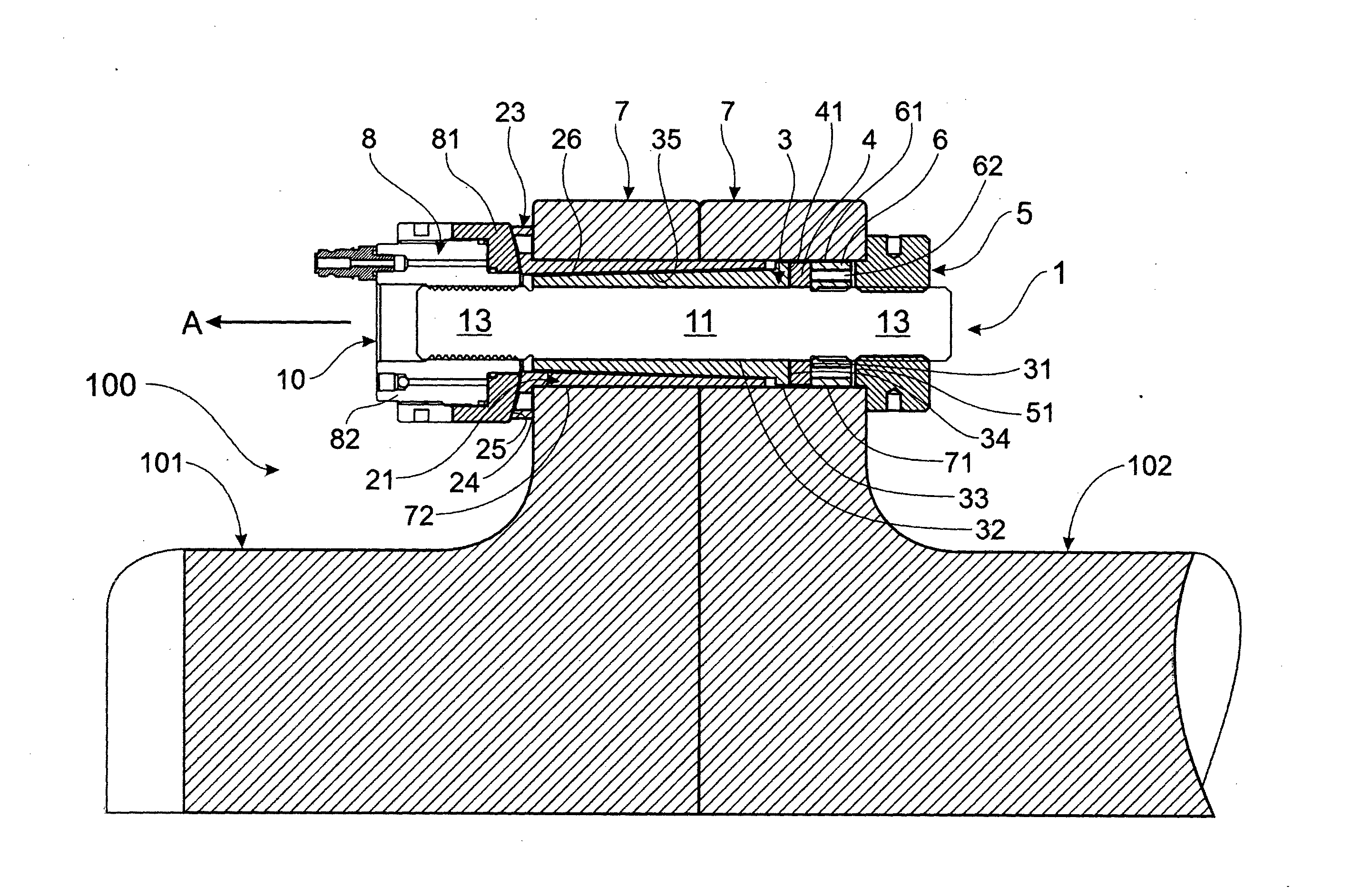
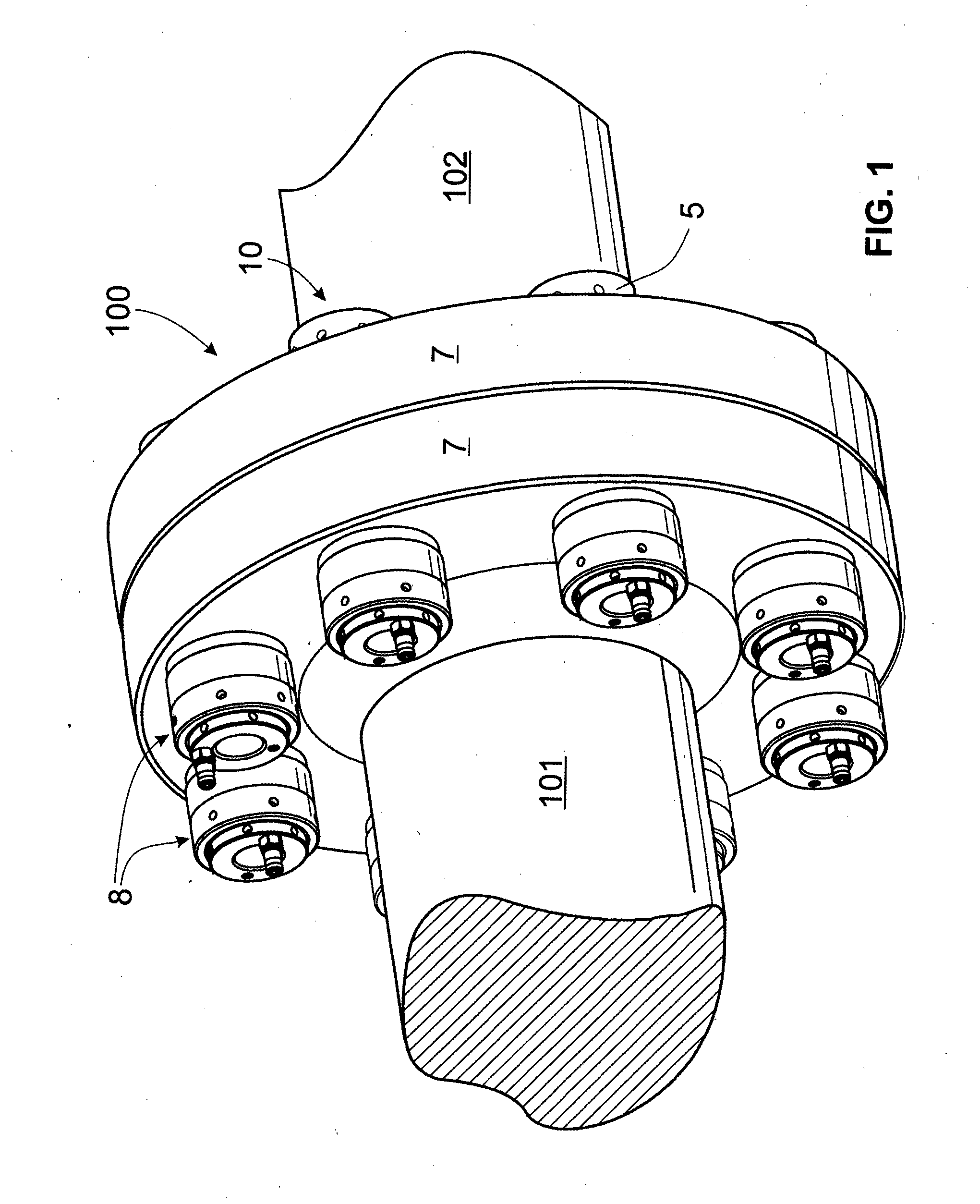
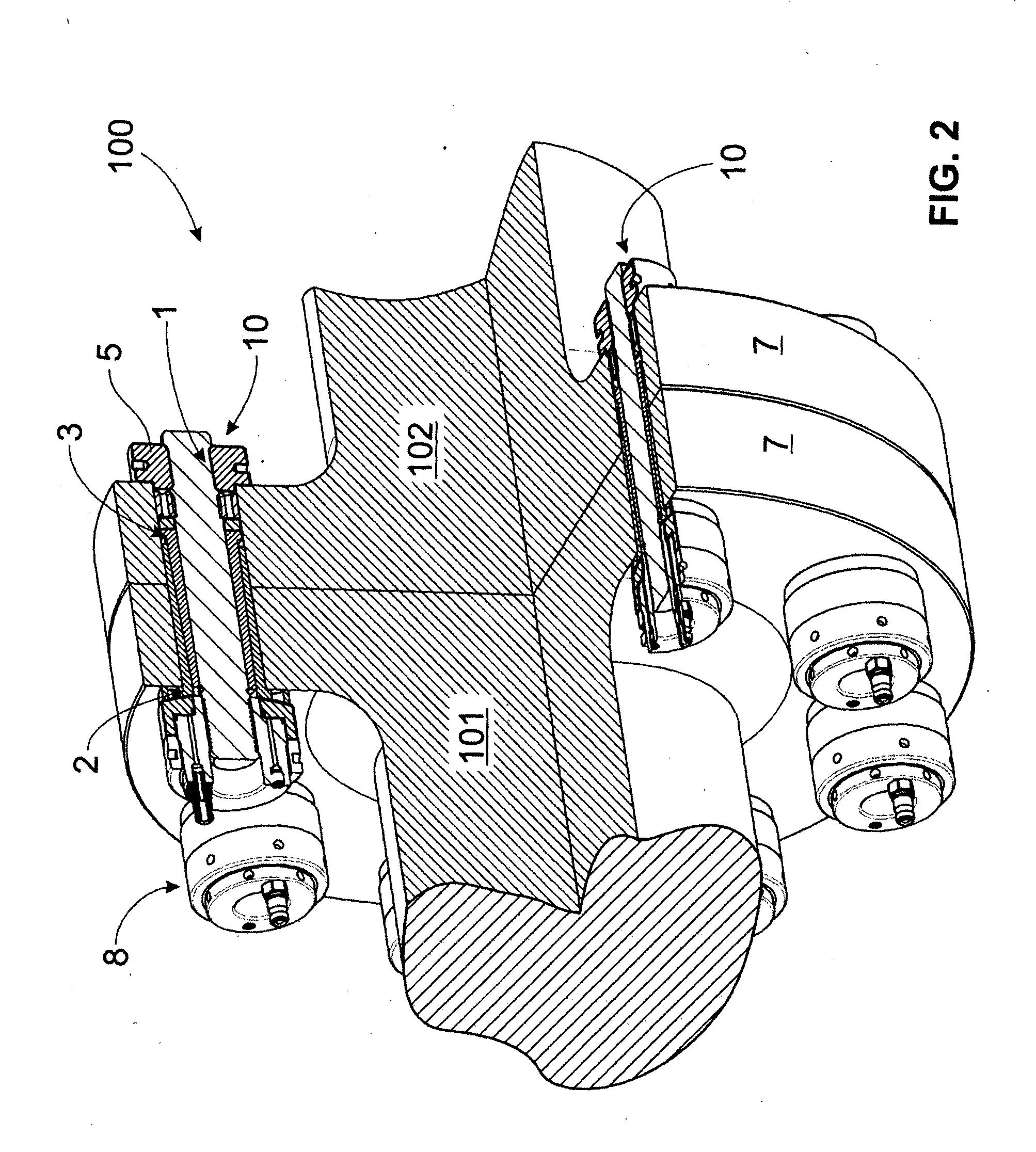
[0057]FIG. 3 illustrates the present invention, where each high-capacity radial fit coupling bolt (or expanded sleeve bolt) 10, is provided with a hydraulic nut 8, e.g., of the type manufactured and sold by Technofast Industries Pty Ltd, 2 / 677 Boundary Road, Richlands, Queensland, Australia, under the Registered Trade Mark “TECHNOFAST”.

[0058]The coupling bolt 10 has a shank 1 with a cylindrical central portion 11 intermediate screw-threaded first and second end portions 12, 13.

[0059]A head nut 5 is screw-threadably engaged with the first end portion 12 of the shank 1 and has an annular end portion 51 on its inner face. The skilled addressee will note that the annular end portion 51 on the head nut 5 is received within a cavity defined by the bolt hole 71 of the first of the components 7 and the shank 1.

[0060]An inner sleeve 3 has a tubular body 31 with a cylindrical bore 32 for slidable movement on the central portion 11 of the shank 1. At the end of the body 31 adjacent the first e...

second embodiment

[0072]In a second embodiment, not illustrated, a tensioning (or tail) nut may be interposed between the tensioning apparatus (connected to the second end portion 13 of the shank 1) and the outer sleeve 2. In this embodiment, the tensioning apparatus applies a tensioning load to the shank 1 to cause the inner sleeve 3 to be axially moved along the central portion 11 of the shank 1 to diametrically expand the outer sleeve 2 as hereinbefore described.

[0073]When the desired tensioning load has been applied, the tensioning (or tail) nut is rotated to move along the second end portion 13 in a direction opposite to the direction of arrow A, until it engages the outer abutment face 26 of the outer sleeve 2 to maintain the tensioning load on the shank 1. The tensioning apparatus, e.g., a hydraulic jack, can then be removed.

[0074]In this embodiment, to enable the components 7 to be separated, the tensioning apparatus is reconnected to the second end portion 13 of the shank 1 and a tensioning ...


PUM


Abstract

A high capacity radial-fit coupling bolt (or “expanding sleeve bolt”) has a pair of tapered sleeves about a shank of a bolt to which can be applied a tensioning load. An extrudable ring, or a compression ring, is interposed between a head nut or head flange at one end of the shank, and one end of an inner sleeve. A tensioning load is applied to the shank, the inner sleeve causing the outer sleeve to expand diametrically. At a preset load limit, the extrudable ring is extruded through at least one bore in a drive piston between the head nut and the extrudable ring, to allow shank to move relative to the inner sleeve until the tensioning load is fully applied. Alternatively, a drive member is provided between the head nut or head flange and the compression ring, and at a preset limit, the compression ring allows the shank to move relative to inner sleeve until the tensioning load is fully applied. The preset limit will typically correspond to the force required to fully expand the outer sleeve.

Description

CROSS-REFERENCE TO RELATED PATENT APPLICATIONS[0001]The present application is a U.S. national stage application under 35 U.S.C. §371 of PCT Application No. PCT / AU2013 / 000209, filed Mar. 6, 2013, which claims priority to Australian patent application no. 2012900875, filed Mar. 6, 2012, the entireties of which are incorporated herein by reference.BACKGROUND OF THE INVENTION[0002]1. Field of the Invention[0003]This invention relates to high-capacity radial fit coupling bolts. (Such bolts are also known as “expanding sleeve bolts”.)[0004]The invention particularly relates, but is not limited to, high-capacity radial fit coupling bolts used to secure engineering components securely together. Examples of potential uses for the bolts include connecting pipeline flanges, drive couplings, machinery mountings and the like.[0005]2. Prior Art[0006]NB: The following discussion is by way of background information only, and is not to be considered a statement of the common general knowledge (CGK)...

Claims


Application Information

Patent Timeline
IPC IPC(8): F16B2/14F16B7/04F16L23/036F16B7/02
CPCF16B2/14F16L23/036F16B7/0406F16B7/02F16B4/004F16B31/043Y10T403/4958Y10T403/4924F16B2200/506F16B29/00
Inventor BUCKNELL, JOHN WENTWORTH
Owner TECHNOFAST IND
Why Eureka
Try Eureka