Intelligent boom control hydraulic system

a hydraulic system and intelligent technology, applied in the direction of mechanical machines/dredgers, transportation and packaging, hoisting equipment, etc., can solve the problems of mechanical-hydraulic systems having inherent kinematic limitations when operated by controlling cylinder speed, reducing the potential energy of mechanical-hydraulic systems, and reducing fatigue, so as to improve the hydraulic operation efficiency of knuckle boom systems, simplify the input of boom control, and reduce fatigue

Active Publication Date: 2015-01-29
DEERE & CO
View PDF1 Cites 10 Cited by
  • Summary
  • Abstract
  • Description
  • Claims
  • Application Information

AI Technical Summary

Benefits of technology

[0004]A system is disclosed for improving the hydraulic operating efficiency of knuckle boom systems in all operating modes and / or simplifying the boom control inputs such that less skilled operators will be more productive and all operators will experience reduced fatigue from extended periods of operation, again resulting in productivity improvements.

Problems solved by technology

When operating conventional knuckle boom systems today, there are inefficiencies in the system whenever the boom and any lifted load is lowered, i.e. a reduction in their potential energy is dissipated by metering hydraulic oil through an orifice and converting the energy into heat which goes into the machine's hydraulic oil.
Mechanical-hydraulic systems have inherent kinematic limitations when operated by controlling cylinder speeds.
The knuckle boom is a non-linear kinematic system where approximating constant boom system endpoint trajectories and velocities can be challenging.

Method used


Image

  • Intelligent boom control hydraulic system
  • Intelligent boom control hydraulic system
  • Intelligent boom control hydraulic system

Examples


Embodiment Construction

[0016]For the purposes of promoting an understanding of the principles of the novel invention, reference will now be made to the embodiments described herein and illustrated in the drawings and specific language will be used to describe the same. It will nevertheless be understood that no limitation of the scope of the novel invention is thereby intended, such alterations and further modifications in the illustrated devices and methods, and such further applications of the principles of the novel invention as illustrated therein being contemplated as would normally occur to one skilled in the art to which the novel invention relates.

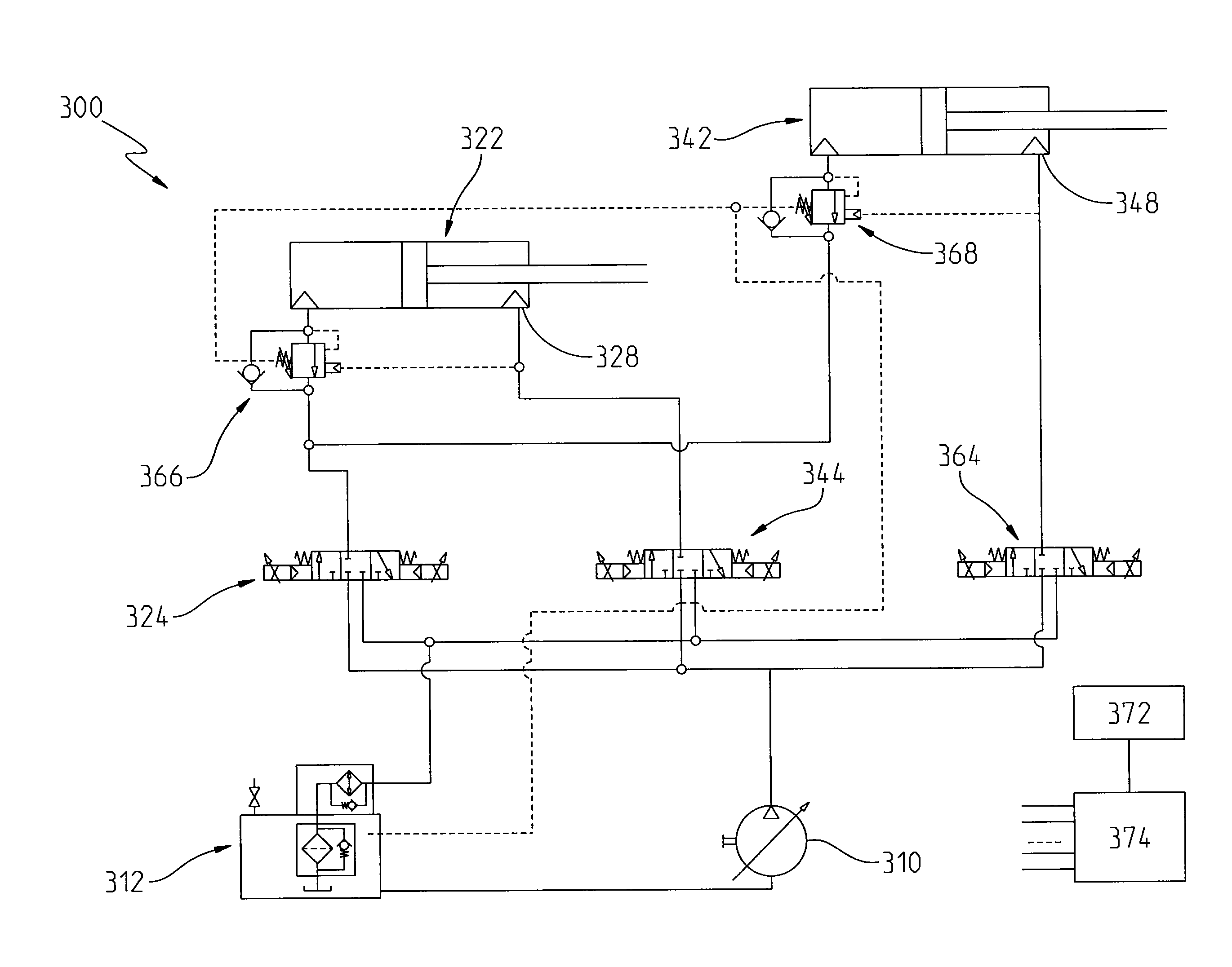
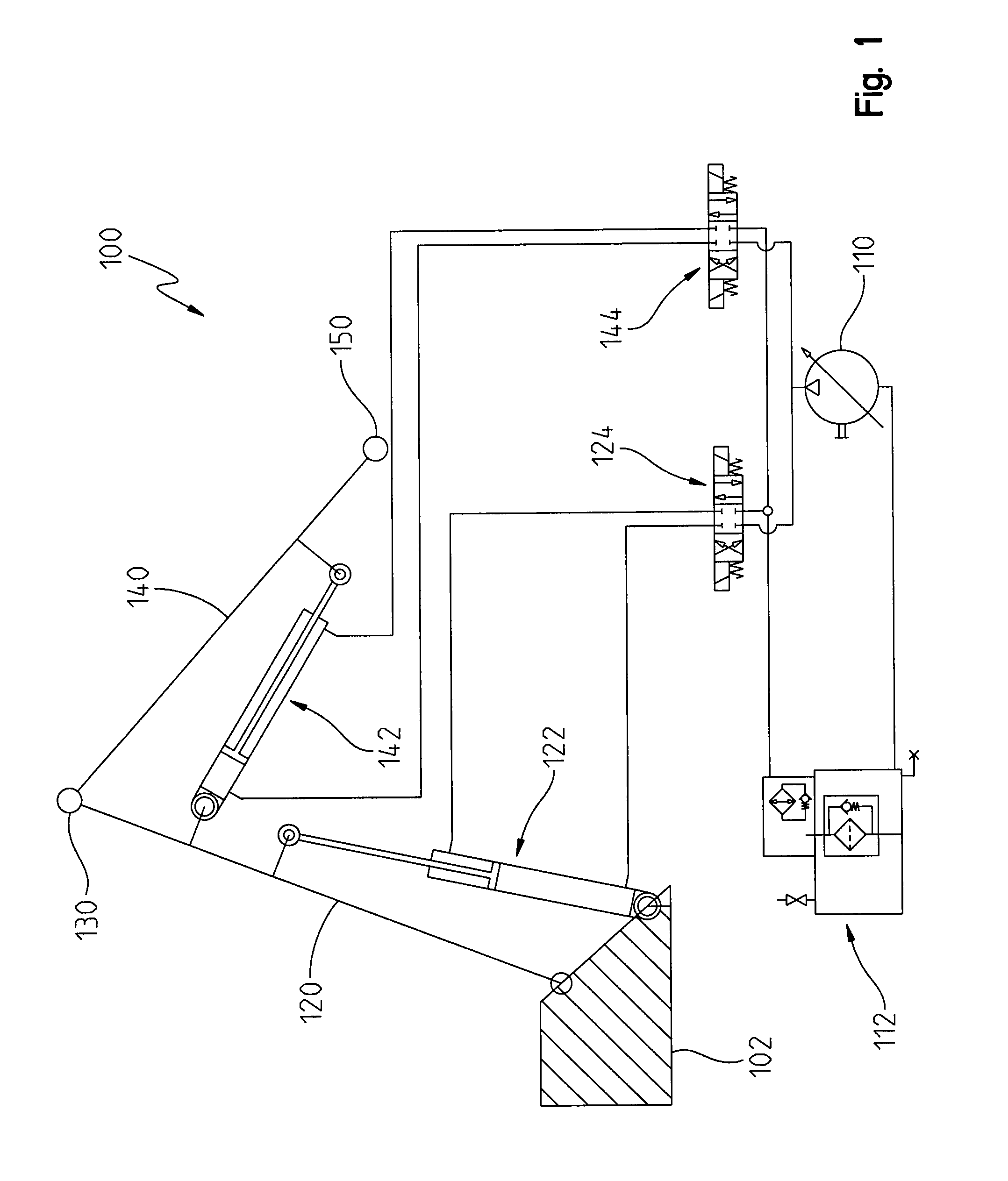
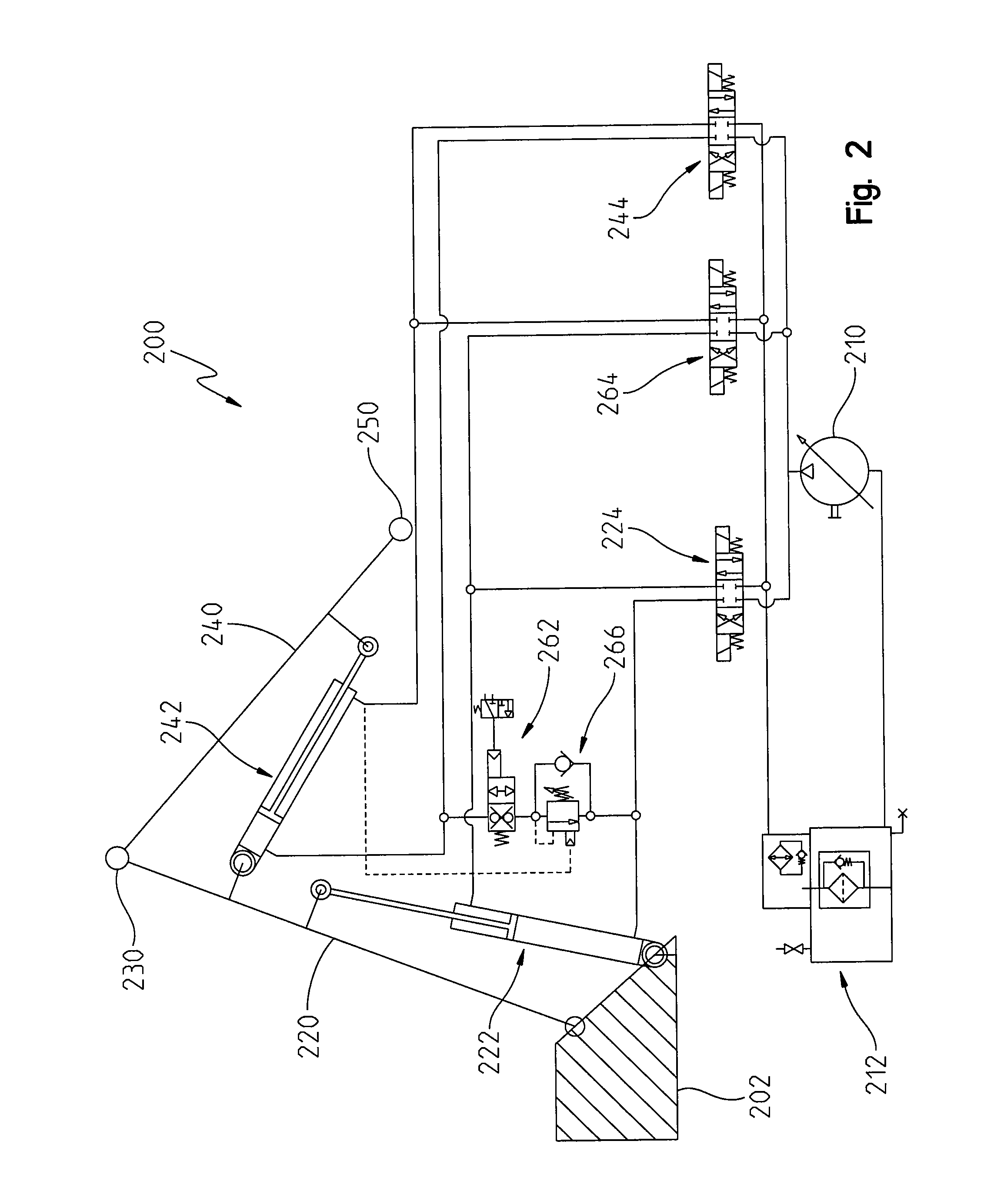
[0017]A boom system can be operated in several different modes. The following table summarizes operational modes enabled by the exemplary knuckle boom hydraulic systems illustrated in FIGS. 1-4.

Hydraulic Circuit ConventionalStraight LineIBC IBC Circuit +CircuitCircuitCircuitAccumulatorOperation Mode(FIG. 1)(FIG. 2)(FIG. 3)(FIG. 4)Joint ModeXXXX(JM)Rapid ...


PUM


Abstract

An intelligent knuckle boom control system is disclosed where hoist and stick cylinders raise and lower main and stick booms, respectively, a base end control valve controls flow to the hoist and stick cylinder base ends, a hoist rod control valve controls flow to the hoist cylinder rod end, and a stick rod control valve controls flow to the stick cylinder rod end. A microprocessor computes control signals to direct flow through the control valves based on operator commands and boom position readings. The system can include an energy storage system for storing excess energy and releasing the stored energy, where the microprocessor directs storage of excess energy and release of stored energy. The energy storage system can include a hydraulic accumulator, an accumulator control valve and hydraulic pressure sensors; where the microprocessor receives pressure sensor readings and computes accumulator control valve control signals.

Description

FIELD OF THE INVENTION[0001]The present invention generally relates to the field of motorized machinery, and more specifically to a hydraulic circuit for a machine with a knuckle boom powered by hydraulic cylinders.BACKGROUND OF THE INVENTION[0002]When operating conventional knuckle boom systems today, there are inefficiencies in the system whenever the boom and any lifted load is lowered, i.e. a reduction in their potential energy is dissipated by metering hydraulic oil through an orifice and converting the energy into heat which goes into the machine's hydraulic oil. Cooling systems need to be added to the machine to expel this heat to ambient air so the hydraulic oil does not overheat.[0003]Mechanical-hydraulic systems have inherent kinematic limitations when operated by controlling cylinder speeds. The knuckle boom is a non-linear kinematic system where approximating constant boom system endpoint trajectories and velocities can be challenging. To raise a boom and load, typically...

Claims


Application Information

Patent Timeline
Patent Type & Authority Applications(United States)
IPC IPC(8): B66C23/82E02F9/22E02F3/43
CPCB66C23/82E02F9/2278E02F9/2217E02F3/435B66C23/54E02F3/436E02F9/2296F15B21/14F15B2211/20546F15B2211/3059F15B2211/50581F15B2211/6658F15B2211/88
Inventor STULEN, HENRY J.RASZGA, CALIN
Owner DEERE & CO
Why Eureka
Try Eureka