Game Controller for a Portable Computing Device

a portable computing and game controller technology, applied in computing, indoor games, instruments, etc., can solve the problems of consuming a large amount of power, consuming a large amount of the battery life of the smart phone, and often providing a limited number of input mechanisms for the smart phone. achieve the effect of improving the user experien

Inactive Publication Date: 2015-01-29
IMMERSA LABS
View PDF7 Cites 45 Cited by
  • Summary
  • Abstract
  • Description
  • Claims
  • Application Information

AI Technical Summary

Benefits of technology

[0009]The game controller assembly is particularly advantageous. For example, there are some features, such as the design of shoulder buttons, which have benefits or purposes that suit particularly well a controller for a smart phone. For example, the controller includes two pairs of shoulder buttons that pivot on alternating axis. The back shoulder button pivots on a front-to-back axis, while the top shoulder button pivots 90° (ninety degree) on a left-to-right axis. This is a purposeful, custom design to solve a space-constraint problem and provide a better user experience. Other benefits are described below in the specification and will be apparent from review of the drawings.

Problems solved by technology

However, unlike videogame controllers built for and connected to game consoles, smart phones often provide a limited number of input mechanisms.
For example, most smart phones do not include a joystick type of input and are limited to a touch screen and one or two input buttons.
Another problem with using smart phones for playing video games is the consumption of power.
When smart phones run video games for that amount of time, this consumes much of the battery life of the smart phone and can significantly impact the power available to the smart phone to before other types of operations.
Yet another problem with using smart phones to play video games is that they are optimized for portability in size and shape.
That optimization in size and shape for portability by the user constantly, conflicts with the needs of the game controller different types of buttons, raised buttons, and other ergonomic features associated with the game controller.

Method used


Image

  • Game Controller for a Portable Computing Device
  • Game Controller for a Portable Computing Device
  • Game Controller for a Portable Computing Device

Examples


first embodiment

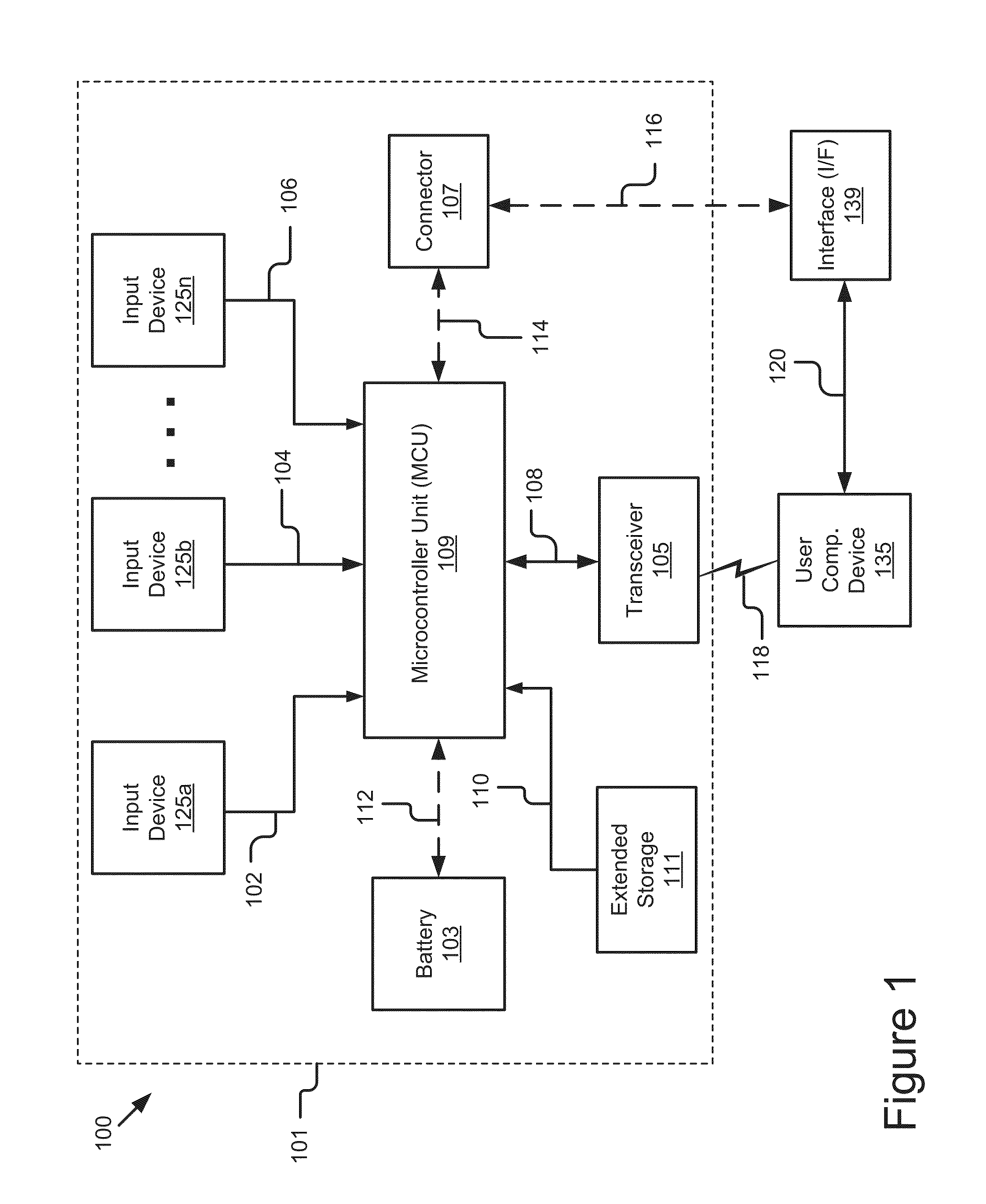
[0061]FIG. 1 illustrates a block diagram of a gaming system 100 including a game controller assembly 101 according to a The illustrated system 100 includes a game controller assembly 101, a user computing device 135 and an interface (I / F) 139. In the illustrated embodiment, the game controller assembly 101 includes one or more input devices 125a, 125b, 125n (referred to individually or collectively as input 125 device) that are from one or more users (not pictured), a microcontroller unit (MCU) 101, a transceiver 105, a battery 103, a connector 107 and extended storage 111.

[0062]The plurality of input 125 devices are provide to allow the user to input commands. Examples of the input devices 125 are further detailed below and in the remaining figures a may include various buttons, triggers buttons, toggle switches, push buttons, microphones, etc. Those skilled the art will recognize that these input devices as buttons are merely one embodiment for the plurality of input devices 125a...

second embodiment

[0096]Referring now to FIG. 9, depicted is game controller assembly 900 illustrating a port 902 for charging. The port 902 in the figure is an outlined location for the port 902 that would charge the game controller assembly's battery and charge the user device's battery. The port 902 is preferably a mini-USB port for charging the game controller assembly 900. The port 902 is position near the end of the game controller assembly 900. It should be understood that the port 902 could alternatively be on any side of the game controller assembly 900 in other locations.

Methods

[0097]FIG. 10 is a flow diagram illustrating a method 1000 of power management for the game controller assembly 101 and the user computing device 135 according to one embodiment. In the illustrated embodiment, the method 1000 includes connecting 1002 the game controller assembly 101 to a user computing device 135 (e.g., a phone). The method 1000 also includes charging 1004 a Lithium Ion Battery of the game controller...

fourth embodiment

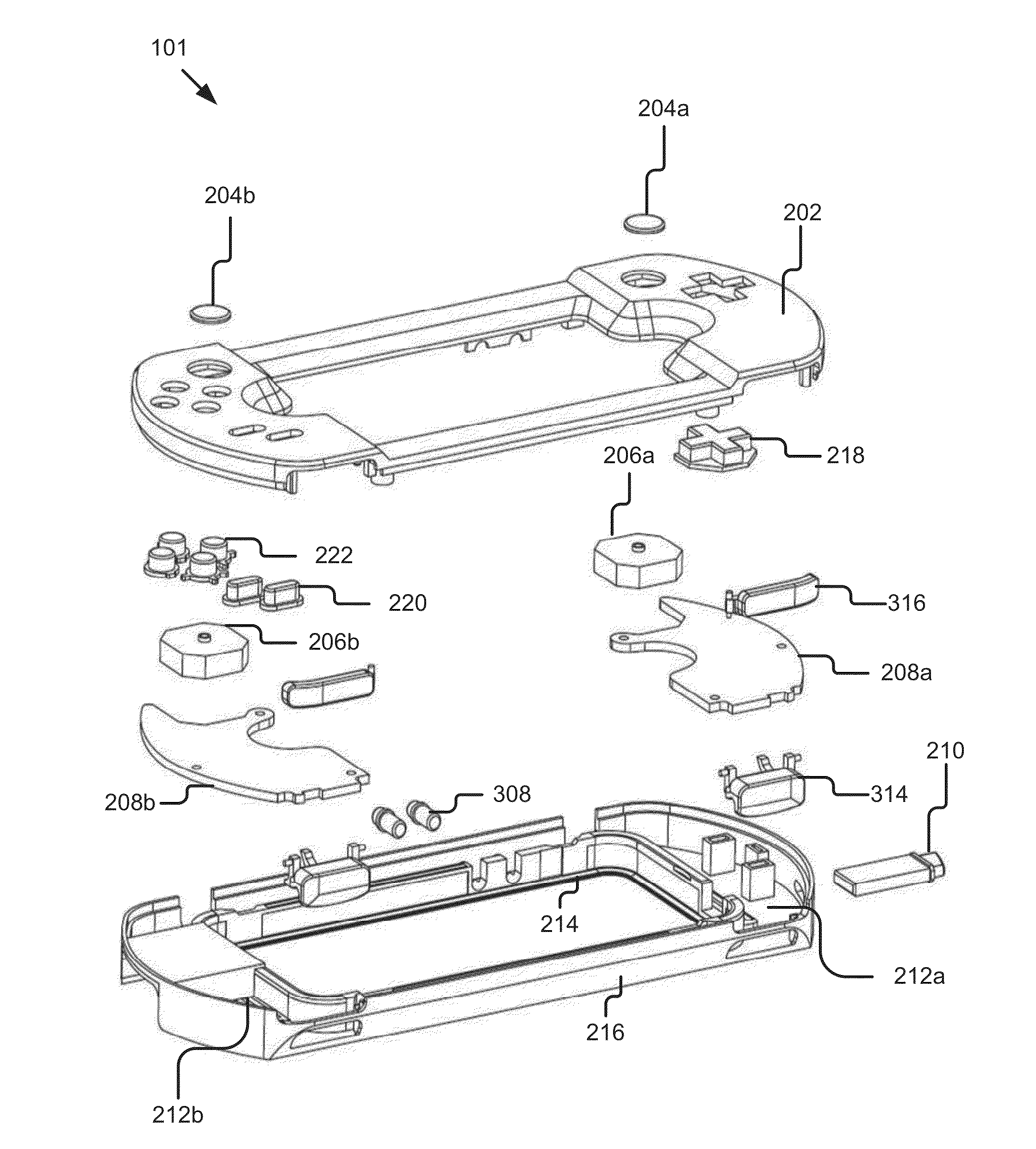
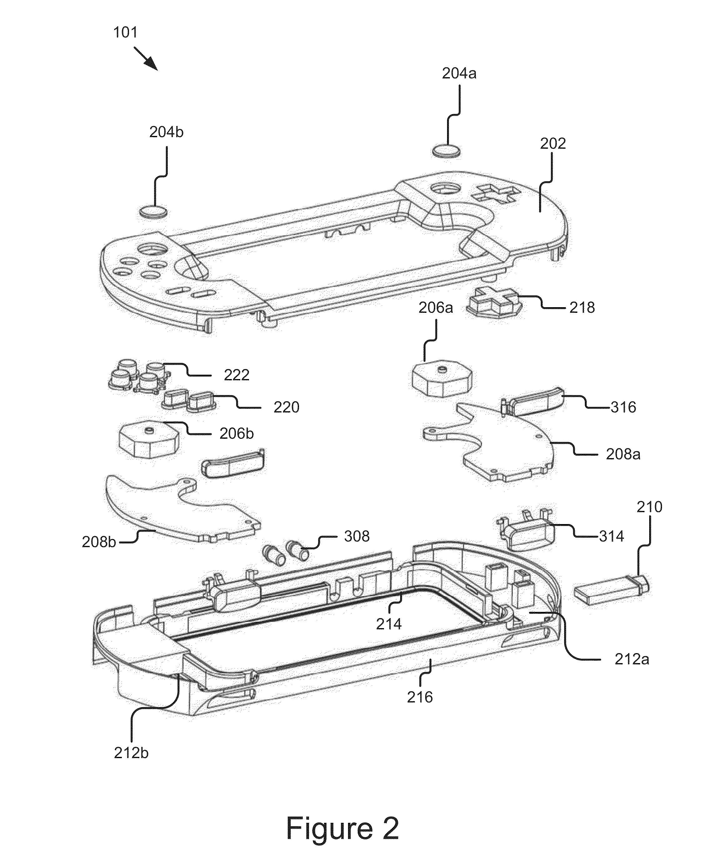
[0106]FIG. 11B shows a top view of the game controller assembly 1110. This embodiment of the game controller 1110 is similar to prior embodiments; however, the buttons 204, 222 and directional pad 218 are modified in position, the top chassis member 202 provides additional audio ducts 1114 for audio signals and a pause button 1112 is provided. The joysticks 204 are positioned closer to the longitudinal axis of the game controller assembly 1110 along the left and right side portions. Additionally, the directional pad 218 is positioned on an opposite side of the longitudinal axis of the game controller assembly 1110 from the joystick 204a. Similarly, the third set of buttons 222 is also positioned on an opposite side of the longitudinal axis of the game controller assembly 1110 from joystick 204b. The pause button 1112 is provided positioned between the joystick 204b and the third set of buttons 222. Finally, audio ducts 1114 are provided to provide a waveguide for sounds to travel fr...


PUM


Abstract

A game controller assembly is mechanically and communicatively connected to a user computing device to be used to play games. The game controller assembly is detachable he coupled mechanically and electrically to the user computing device. For example, the user computing device may be a smart mobile phone. The game controller assembly can be mounted on the smart mobile phone and also be communicatively coupled to the smart phone for communications with the smart phone. The game controller is used to play games on the smart phone. The game controller assembly can also be used for other purposes, such as navigating web pages, watching video streams, interacting with other online users, interacting/socializing, etc.

Description

CROSS REFERENCE TO RELATED APPLICATIONS[0001]This application claims the benefit under 35 U.S.C. §119(e) of U.S. Provisional Application No. 61 / 858,191, entitled “GAME CONTROLLER ASSEMBLY,” filed on Jul. 25, 2013, the entire contents of which are incorporated herein by reference; of U.S. Provisional Application No. 61 / 943,470, entitled “EXTENSIONS AND ENHANCEMENTS TO GAME CONTROLLER ASSEMBLY” filed on Feb. 23, 2014, the entire contents of which are incorporated herein by reference; and of U.S. Provisional Application No. 62 / 004,814, entitled “GAME CONTROLLER WITH LOCKING MECHANISM TO RECEIVE ENCASED PORTABLE COMPUTING DEVICE,” filed on May 29, 2014, the entire contents of which are incorporated herein by reference.BACKGROUND OF THE INVENTION[0002]The present invention relates to video game controllers. More particularly, the present invention relates to a game controller for a portable computing device. Still more particularly, the present invention relates to a game controller with...

Claims


Application Information

Patent Timeline
Patent Type & Authority Applications(United States)
IPC IPC(8): A63F13/24A63F13/92
CPCA63F13/92A63F13/24A63F13/23
Inventor RUNDELL, PATRICK JOSEPHMATZKE, CAMERON ERICHBALDWIN-BROWN, LUKE JAMES
Owner IMMERSA LABS
Why Eureka
Try Eureka