
Organic electroluminescence element

Inactive Publication Date: 2015-02-05
PANASONIC INTELLECTUAL PROPERTY MANAGEMENT CO LTD
View PDF4 Cites 6 Cited by
  • Summary
  • Abstract
  • Description
  • Claims
  • Application Information

AI Technical Summary

Benefits of technology

The present invention provides an organic electroluminescence element that has a structure where an electrode made of electrically conductive polymer material allows light transmission and improves the efficiency and reliability of light output.

Problems solved by technology

However, depending on a size or a location of a desiccant, this desiccant may be opaque.

Method used


Image

  • Organic electroluminescence element
  • Organic electroluminescence element
  • Organic electroluminescence element

Examples


example 1

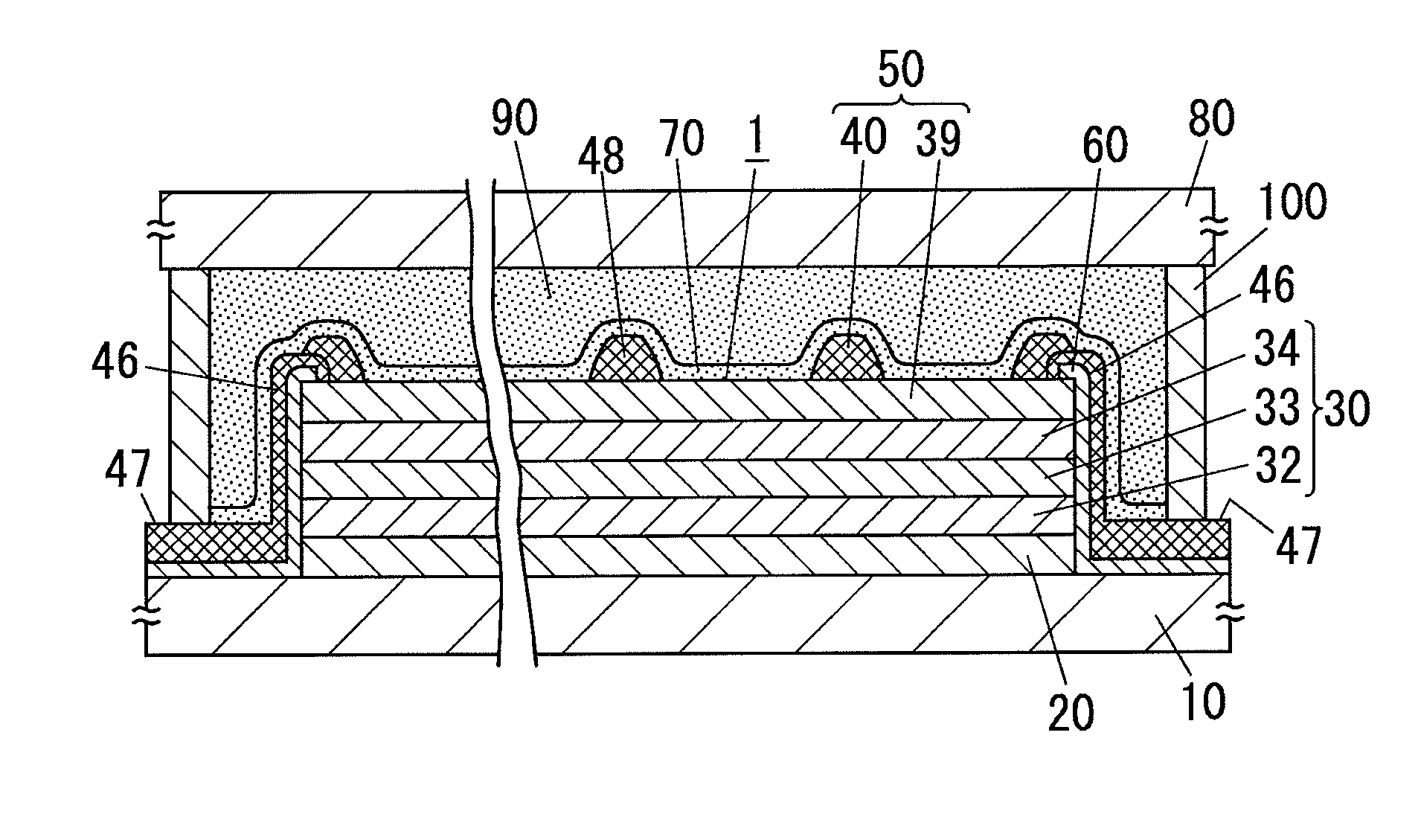
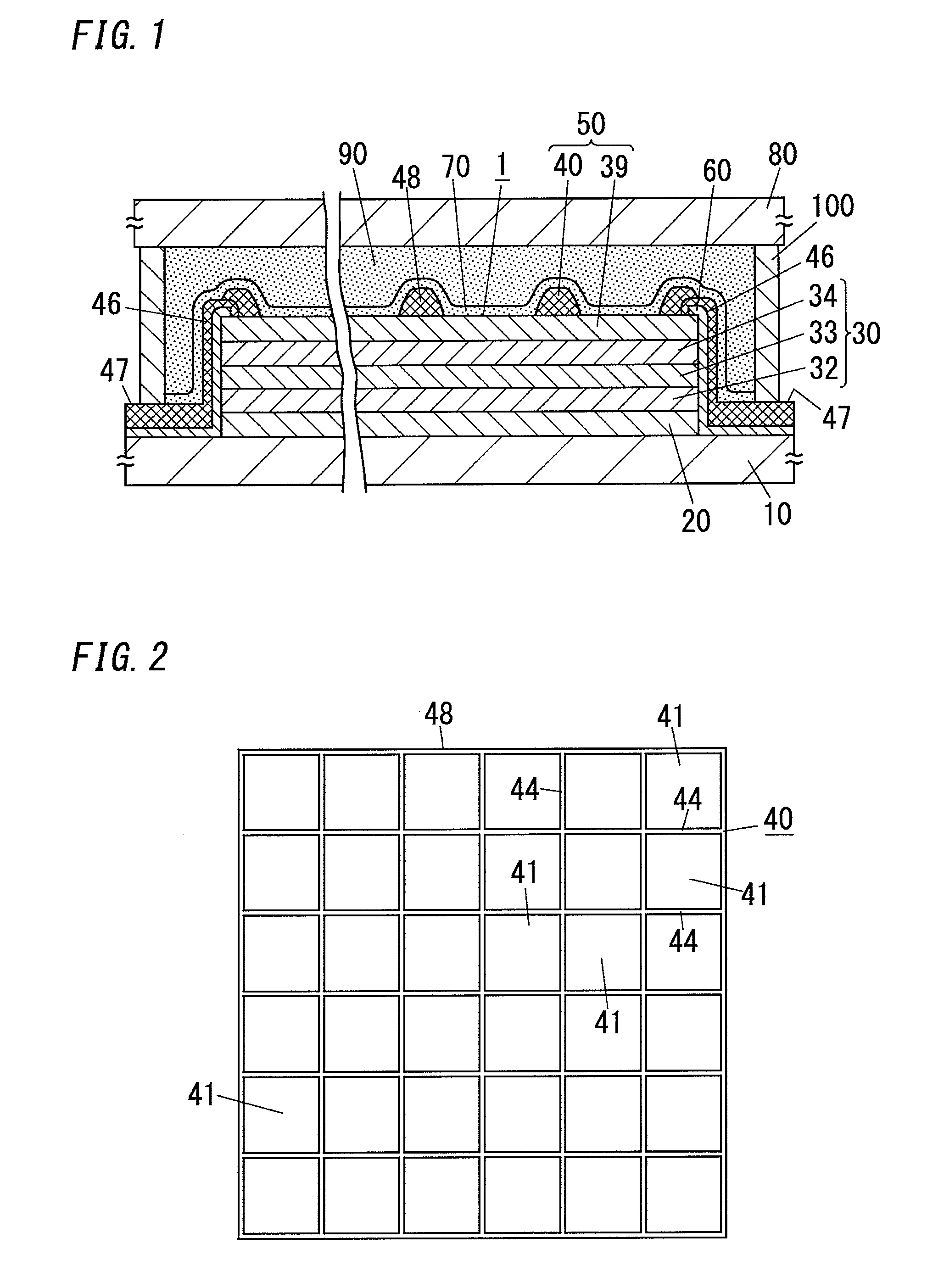
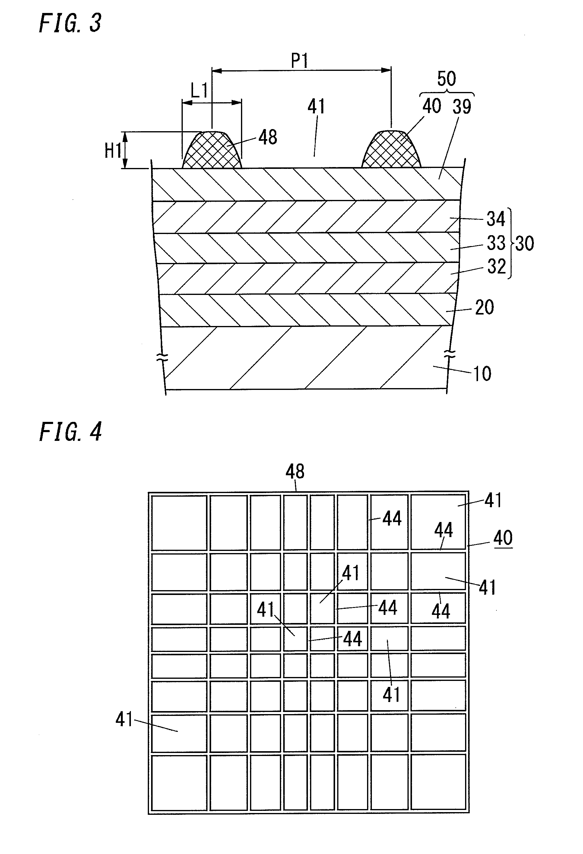
[0096]The organic electroluminescence element having the structure as shown in FIG. 1 was manufactured as Example 1.

[0097]Manufacturing conditions of the organic electroluminescence element of Example 1 are as follows.

[0098]To manufacture the organic electroluminescence element of Example 1, the first step was performed. In the first step, first a non-alkali glass plate (No. 1737 available from Corning Incorporated) with a thickness of 0.7 mm was prepared as the substrate 10 and a cathode serving as the first electrode 20 of aluminum film having a thickness of 80 nm was formed on the surface of the substrate 10 by a vacuum vapor deposition method.

[0099]After the first step, the second step of forming the functional layer 30 was performed. In the second step, the light-emitting layer 32, the hole transport layer serving as the carrier transport layer 33, and the hole injection layer serving as the carrier injection layer 34 were formed sequentially.

[0100]In the process of forming the...

example 2

[0108]The organic electroluminescence element of Example 2 was prepared to have the same structure as the organic electroluminescence element of Example 1, except the transparent protection layer 70 of the present example had a thickness of 40 nm.

example 3

[0109]The organic electroluminescence element of Example 3 was prepared to have the same structure as the organic electroluminescence element of Example 1, except the transparent protection layer 70 of the present example had a thickness of 25 nm.


PUM


Abstract

The organic electroluminescence element includes a functional layer which is interposed between the first electrode and the second electrode and includes a light-emitting layer. The second electrode includes at least an electrically conductive polymer layer which is in contact with the functional layer and has a light transmissive property. The organic electroluminescence element includes: a substrate; a sealing substrate with a light transmissive property; a transparent protection layer covering an element part including a stack of the first electrode, the functional layer and the second electrode; and a resin layer which is interposed between the transparent protection layer and the sealing substrate and has a light transmissive property.

Description

TECHNICAL FIELD[0001]The present invention relates to organic electroluminescence elements.BACKGROUND ART[0002]Recently, organic electroluminescence elements are attracting attention as next-generation light emitting devices because of various advantages that such organic electroluminescence elements enable surface emission, can be mercury-free, can operate at low temperature, can be made at low cost, can be lighter, and can be flexible.[0003]As such organic electroluminescence elements, there has been proposed an organic electroluminescence light-emitting device having a structure shown in FIG. 6 (document 1 [JP 2008-181832 A]), for example.[0004]In this organic electroluminescence light-emitting device, a transparent conductive layer 102 is placed on a surface of a light transmissive substrate 101, an organic light-emitting layer 103 is placed on the transparent conductive layer 102, and a cathode layer 104 is placed on the organic light-emitting layer 103. Further, this organic e...

Claims


Application Information

Patent Timeline
IPC IPC(8): H01L51/52
CPCH01L51/5203H01L51/5256H05B33/04H05B33/28H10K50/824H10K50/828H10K50/8426H10K50/844H10K2102/3026H10K50/8445H10K50/805
Inventor NAKATA, MANABUYAMAKI, TAKEYUKINAKAMURA, MASAHIROYAMANA, MASAHITO
Owner PANASONIC INTELLECTUAL PROPERTY MANAGEMENT CO LTD
Features
  • Generate Ideas
  • Intellectual Property
  • Life Sciences
  • Materials
  • Tech Scout
  • Unparalleled Data Quality
  • Higher Quality Content
  • 60% Fewer Hallucinations
Learn More