Lighting device

a technology of lighting device and light guide plate, which is applied in the direction of lighting and heating apparatus, semiconductor devices for light sources, instruments, etc., can solve the problems of long life span, difficult application of light guide plate, and inability to easily change product plans and designs, so as to reduce the number of light emitting units, the thickness of the lighting device can be thinner, and the effect of ensuring flexibility

Active Publication Date: 2015-02-05
LG INNOTEK CO LTD
View PDF10 Cites 11 Cited by
  • Summary
  • Abstract
  • Description
  • Claims
  • Application Information

AI Technical Summary

Benefits of technology

[0012]According to the present invention, it is advantageous that the number of light emitting units can be reduced and an entire thickness of the lighting device can be thinner by removing the light guide plate and guiding light using the resin layer.
[0013]According to the present invention, as the lighting device is formed using the flexible printed circuit board and the resin layer, flexibility can be secured and a degree of freedom in product design can be improved.
[0014]Also, according to the present invention, it is advantageous that the lighting device, which enables the geometric optical pattern to be implemented by further forming the protruding optical pattern at the upper side of the printed circuit board or at the lower side of the diffusion member, can be provided. Furthermore, the light lighting having improved aesthetic sensibility can be provided and can be applied to various kinds of lighting devices.
[0015]Moreover, ac

Problems solved by technology

Unlike a florescent lamp, since the LED device does not use harmful substances such as mercury and the like, it has a low possibility to cause environmental pollution and a long life span compared to a conventional light source.
Furthermore, as a m

Method used


Image

  • Lighting device
  • Lighting device
  • Lighting device

Examples


Embodiment Construction

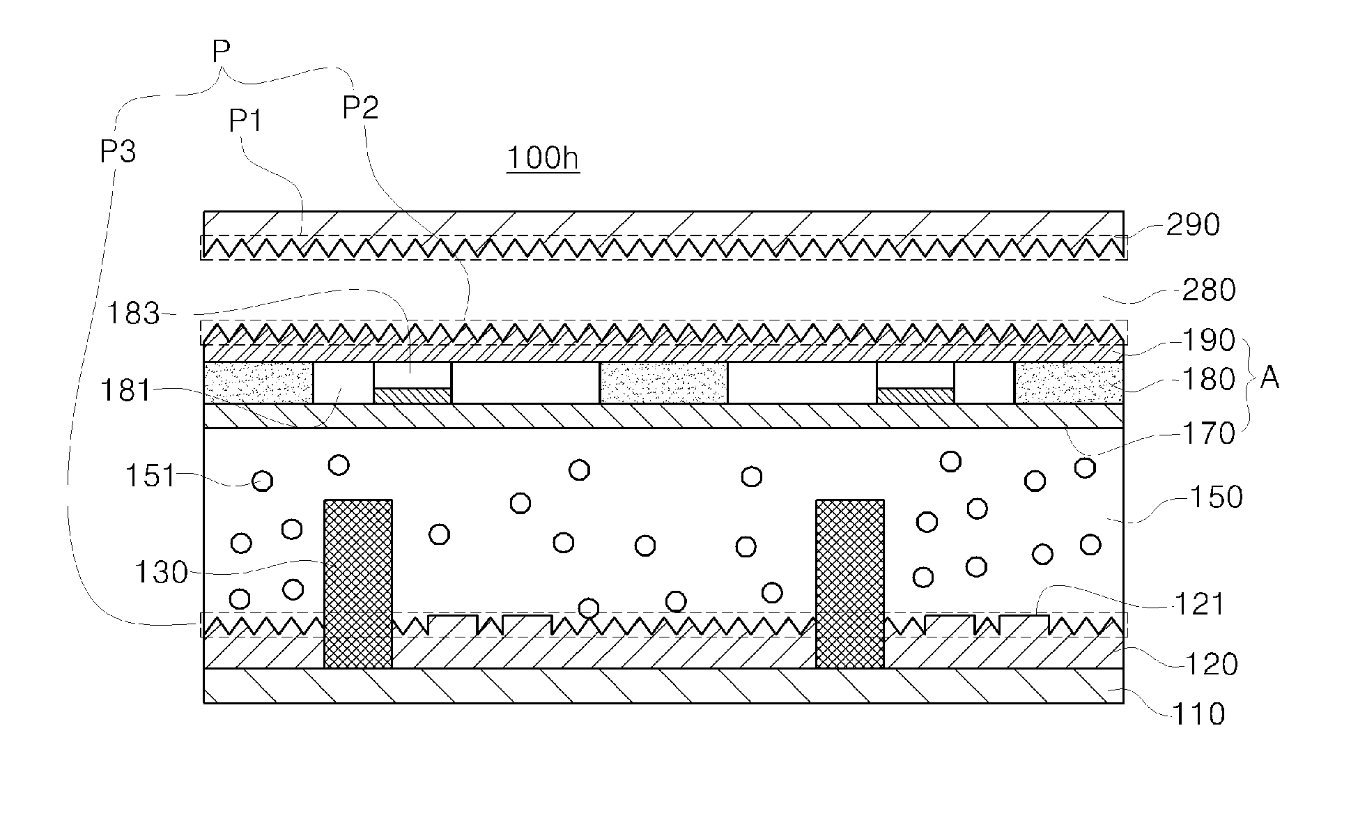
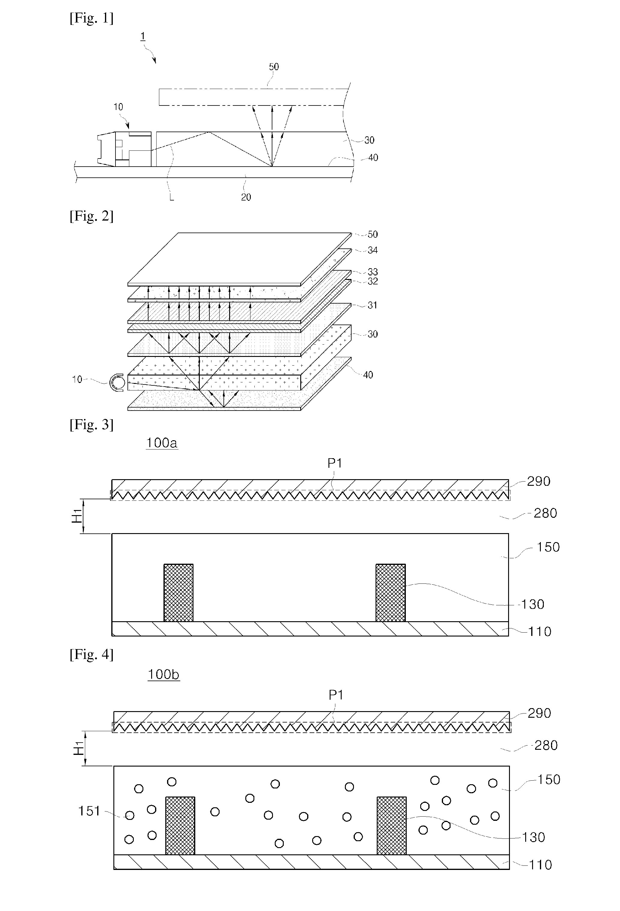
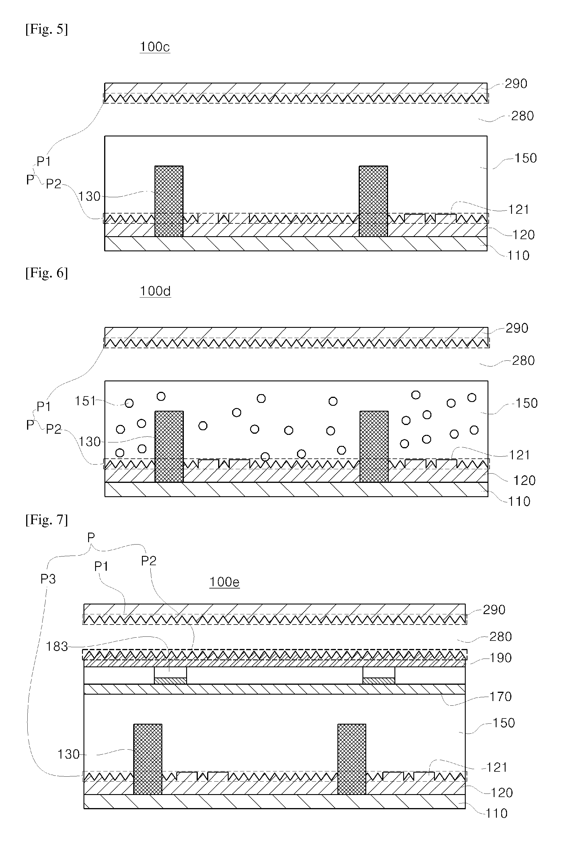
[0024]Exemplary embodiments according to the present invention will now be described more fully hereinafter with reference to the accompanying drawings so that those having ordinary skill in the art can easily embody. This invention may, however, be embodied in different forms and should not be construed as limited to the exemplary embodiments set forth herein. It is to be understood that the form of the present invention shown and described herein is to be taken as a preferred embodiment of the present invention and that various changes and modifications may be made in the invention without departing from the spirit and scope thereof. Also, in the following description, it is to be noted that, when the functions of conventional elements and the detailed description of elements related with the present invention may make the gist of the present invention unclear, a detailed description of those elements will be omitted. Reference will now be made in greater detail to a preferred emb...


PUM

PropertyMeasurementUnit
Lengthaaaaaaaaaa
Flexibilityaaaaaaaaaa
Shapeaaaaaaaaaa

Abstract

Provided is a lighting device, including: one or more light emitting units formed on a printed circuit board; a resin layer which is formed on the light emitting units so that the light emitting units are embedded in the resin layer; and a diffusion member formed on an upper side of the resin layer, wherein a protruding optical pattern is formed on at least one of an upper side of the printed circuit board and a lower surface of the diffusion member, whereby various geometric optical patterns can be implemented, an entire thickness can be reduced and when a product is designed, a degree of freedom in design can be improved according to the securing of flexibility.

Description

TECHNICAL FIELD[0001]The present invention relates to a technical field of a lighting device, and more specifically, to a structure of a lighting device which enables an entire thickness to get thinner and is able to secure light efficiency and embody various optical patterns by removing a light guide plate.BACKGROUND ART[0002]An LED (Light Emitted Diode) device is a device which converts an electrical signal to infrared rays or light using a composition semiconductor property. Unlike a florescent lamp, since the LED device does not use harmful substances such as mercury and the like, it has a low possibility to cause environmental pollution and a long life span compared to a conventional light source. Also, it is advantageous that the LED device spends low electricity compared to the conventional light source and has excellent visibility and low brilliantness due to a high color temperature.[0003]Accordingly, a current lighting device has been developed from a structure, in which a...

Claims


Application Information

Patent Timeline
IPC IPC(8): F21K99/00
CPCF21K9/50G02B6/0021G02B6/0041G02B6/0051G02B6/0016G02B6/0053F21K9/60F21K9/62F21V13/08F21V3/062F21V17/101F21V14/006F21Y2115/10H05K2201/05
Inventor YANG, HYUN DUCKPARK, MOO RYONGPARK, KWANG HO
Owner LG INNOTEK CO LTD
Why Eureka
Try Eureka