System and Method for Controlling a Heat Pump for a Swimming Pool

a technology for controlling a heat pump and a swimming pool, which is applied in the direction of heating fuel, space heating and ventilation details, domestic heating details, etc., can solve the problems of large energy consumption of devices, significant electrical consumption required to heat and maintain the water of a swimming pool at an agreeable temperature, and inability to meet the needs of swimming pool use, etc., to achieve the effect of reducing the noise level

Active Publication Date: 2015-02-12
ZODIAC POOL CARE EURO
View PDF9 Cites 25 Cited by
  • Summary
  • Abstract
  • Description
  • Claims
  • Application Information

AI Technical Summary

Benefits of technology

[0008]The use of such a heat pump that has several non-zero power levels makes it possible to implement various control strategies, according to the parameters that are to be optimized.
[0014]In practice, for domestic heating (heating the air of the house), an all-or-nothing type control leads to stoppages and restarts that are very close together in time (for example every few minutes), and it is the stopping and the starting of the compressor which provokes its premature ageing. It is therefore desirable to reduce the number of compressor stoppages / restarts. For this, the inverter heat pump technology makes it possible to continuously control the motor of the compressor from zero to its maximum power value, and the heat pump is therefore generally left always running, but by using two power values: a maximum value, and a value close to zero, but non-zero, not causing the compressor to stop. The problem addressed by the present invention is not to reduce the fatigue of the compressor, since the stoppages / restarts of a swimming pool heat pump are few in number in time (several orders of magnitude less numerous than for a domestic heating application, as has just been seen). The choice of a heat pump of inverter type in the present invention is not therefore linked to this problem.
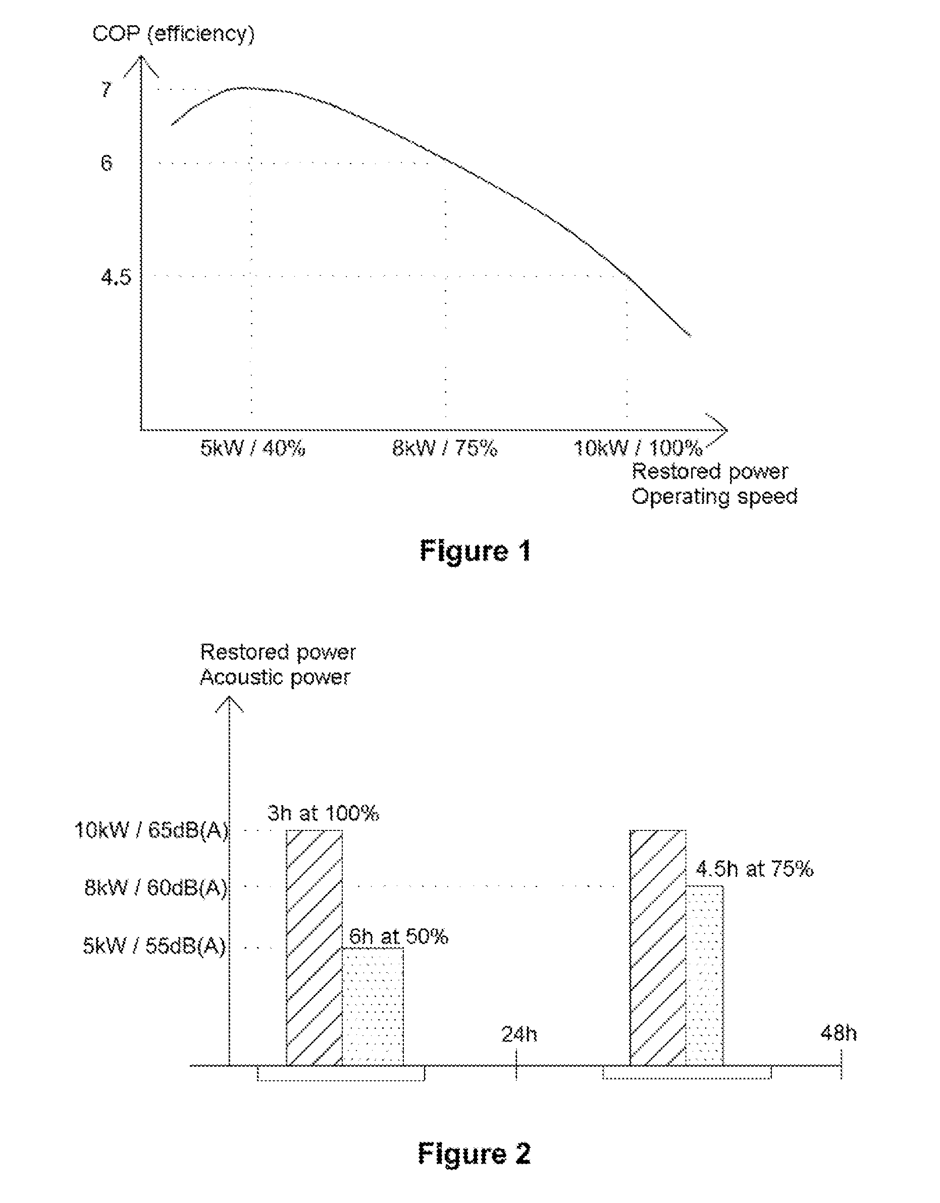
[0017]It is then noted that the noise level of a heat pump is directly linked to the speeds of the compressor and of the fan. The use of at least one non-maximum power level is also reflected in a substantially reduced noise level.
[0020]one of the operating power levels is close to the power level (that is to say the compressor speed) that maximizes the performance coefficient of the heat pump.

Problems solved by technology

These devices consume a lot of energy.
It is in fact in particular a fairly noisy device, because of the presence of a compressor and of a fan.
Moreover, the electrical consumption required to heat and maintain the water of a swimming pool at an agreeable temperature is still significant.

Method used


Image

  • System and Method for Controlling a Heat Pump for a Swimming Pool
  • System and Method for Controlling a Heat Pump for a Swimming Pool
  • System and Method for Controlling a Heat Pump for a Swimming Pool

Examples


Embodiment Construction

[0043]The invention relates to a technical swimming pool environment, for example a sunken swimming pool of family type. This swimming pool is considered to be equipped with a water filtration and recirculation device comprising a circulation pump. Such a circulation pump is run in a programmed manner for several hours a day, generally approximately ten or so hours per day during summer and 2 to 4 hours per day during winter, even zero hours depending on the selected winter mode. The circulation pump is high power, this power being directly linked to the volume of the swimming pool and to the filtration device used (for example sand filter), typically allowing for a flow of 5 to 15 m3 of water per hour in the filter and the swimming pool.

[0044]The swimming pool heating system as described here by way of nonlimiting example comprises, firstly, a heat pump positioned on a branch from the filtration water flow. Conventionally, such a heat pump can be run only when the circulation pump ...


PUM


Abstract

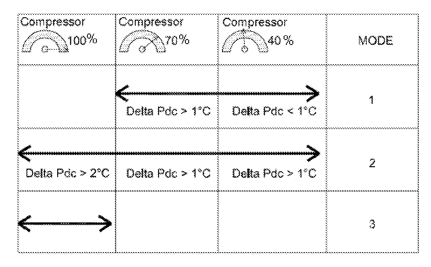
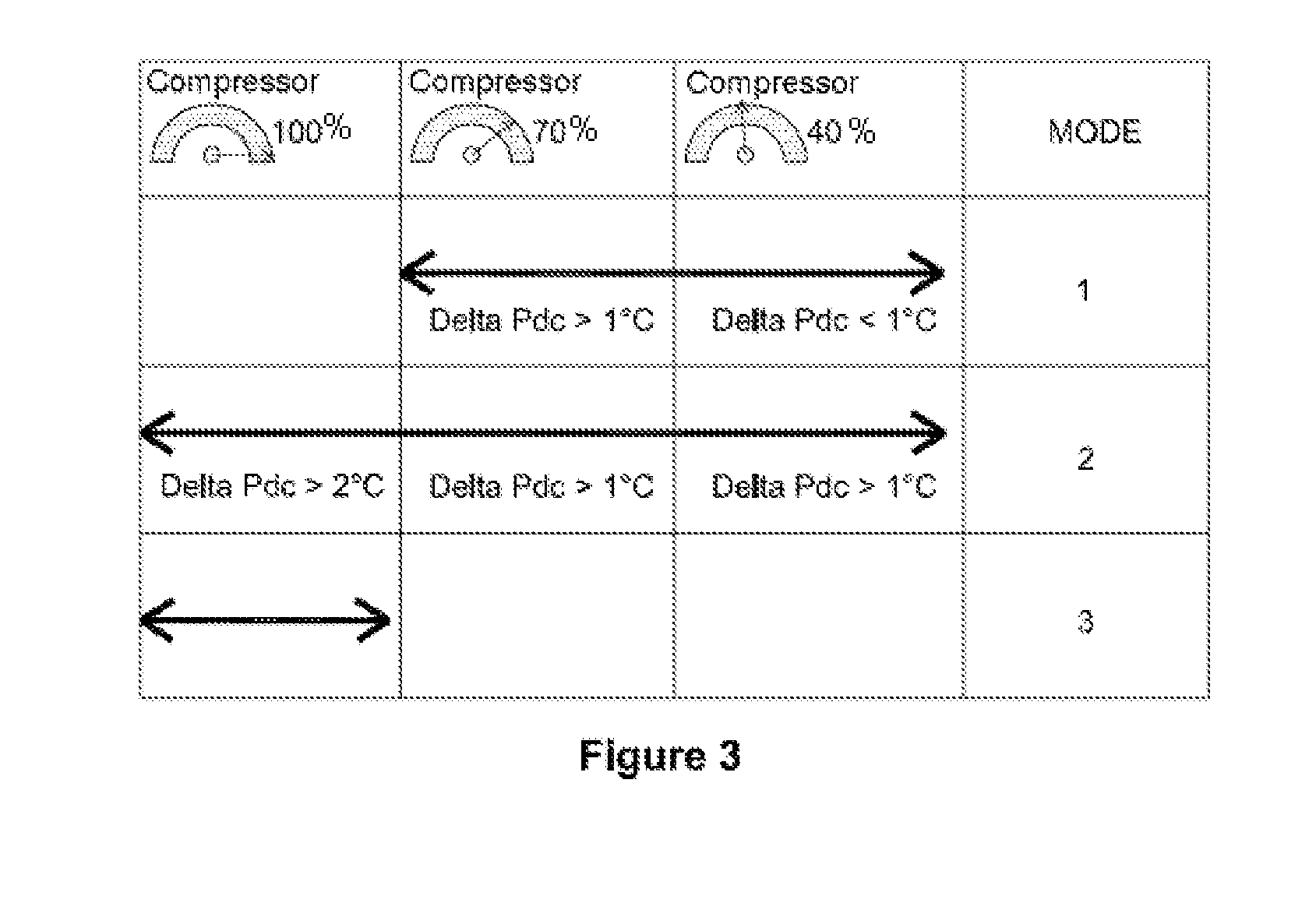
The invention relates to a swimming pool heating system, characterized in that it comprises a heat pump and means for controlling the compressor of said heat pump according to a number of non-zero power levels, as a function of a predetermined set of parameters. The system comprises, for example, three power levels, the first level being close to 40% of the compressor speed, the second level being close to 70% of the compressor speed, and the third level being close to 100% of the maximum compressor speed.

Description

[0001]The present invention relates to the field of swimming pool equipment. It relates more particularly to a heating system and a method for controlling a heat pump intended to reheat the water of a swimming pool.PREAMBLE AND PRIOR ART[0002]When a swimming pool is to be used outside the summer period, it is necessary to provide a device for heating the water of the swimming pool. This makes it possible to extend its period of use by several months and improve usage comfort in the summer period. The first swimming pool heating devices consisted of conventional boilers, or of devices using resistors to heat a flow of water.[0003]These devices consume a lot of energy. Because of this, the use of heat pumps to reheat the water of a swimming pool was introduced some years ago. It does, however, come up against various drawbacks. It is in fact in particular a fairly noisy device, because of the presence of a compressor and of a fan. Moreover, the electrical consumption required to heat ...

Claims


Application Information

Patent Timeline
Patent Type & Authority Applications(United States)
IPC IPC(8): E04H4/12F25B49/02F25B30/02
CPCE04H4/129F25B49/02F25B30/02F24H4/02F24D19/1054F24D2200/123F25B2600/0253F25B49/025F25B2500/12F25B2600/01F25B2600/021F25B2700/21F24F5/0071Y02B30/70F24H1/54
Inventor DELOCHE, REMILEROYER, BRICE
Owner ZODIAC POOL CARE EURO
Why Eureka
Try Eureka