Wireless power transmitting device

a power transmitting device and wireless technology, applied in the direction of transformers, inductances, transportation and packaging, etc., can solve the problems of low efficiency or not at all of power transfer, additional components and complexity, and the cost of producing each charging pad, so as to facilitate the alignment of the wireless receiver, reduce the complexity and the cost of the wireless transmitter, and reduce the ability of a user.

Active Publication Date: 2015-02-12
SANDISK TECH LLC
View PDF16 Cites 11 Cited by
  • Summary
  • Abstract
  • Description
  • Claims
  • Application Information

AI Technical Summary

Benefits of technology

[0006]To facilitate alignment of the wireless receiver and the wireless transmitter, the wireless power transmitting device may include at least one protrusion coupled to a surface of the wireless power transmitting device. The surface may accommodate the wireless power receiving device and may also contain the active area corresponding to the electromagnetic emitting portion. The protrusion is configured as a guide for two sides of the wireless power receiving device to align the wireless receiver with the wireless transmitter. By guiding the wireless power receiving device so that the wireless receiver is aligned with the wireless transmitter, the wireless power transmitting device reduces an ability of a user to make a mistake when placing the wireless power receiving device on the wireless power transmitting device. Accordingly, the wireless transmitter does not need to be designed, e.g., sized or positioned, to account for placement mistakes caused by a user. The active area may be sized and positioned specifically for the wireless power receiving devices that the wireless power transmitting device is designed to accommodate. By sizing and positioning the active area specifically for particular wireless power receiving devices, a complexity and a cost of the wireless transmitter may be limited.

Problems solved by technology

If the user does not correctly place the receiving device on the charging pad (e.g., does not align the receiving device with the designated area), power may be transferred at low efficiency or not at all.
As the number of inductive coils increases, so does a cost of producing each charging pad.
Increasing the charging area requires additional components and complexity for the transmitter, which translates into increased costs for producing the charging pad.
By guiding the wireless power receiving device so that the wireless receiver is aligned with the wireless transmitter, the wireless power transmitting device reduces an ability of a user to make a mistake when placing the wireless power receiving device on the wireless power transmitting device.
By sizing and positioning the active area specifically for particular wireless power receiving devices, a complexity and a cost of the wireless transmitter may be limited.
However, because the single barrier 806 only acts as a guide for a single side of the first wireless power receiving device 610, user mistakes in positioning the first wireless power receiving device 610 along the single barrier 806 may result in misalignment of the active area 810 and the reception area 614.
Additionally, the wireless power transmitting device 800 may be prone to user mistakes when the first wireless power receiving device 610 is to be manually aligned on the single barrier 806.

Method used


Image

  • Wireless power transmitting device
  • Wireless power transmitting device
  • Wireless power transmitting device

Examples


Embodiment Construction

[0022]Particular embodiments of the present disclosure are described below with reference to the drawings. In the description, common features are designated by common reference numbers throughout the drawings.

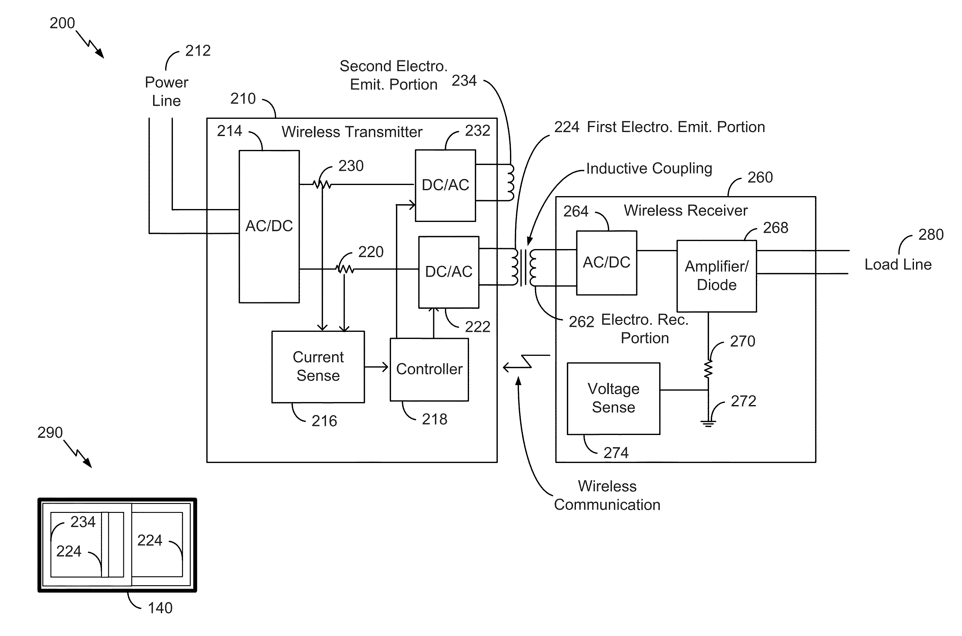
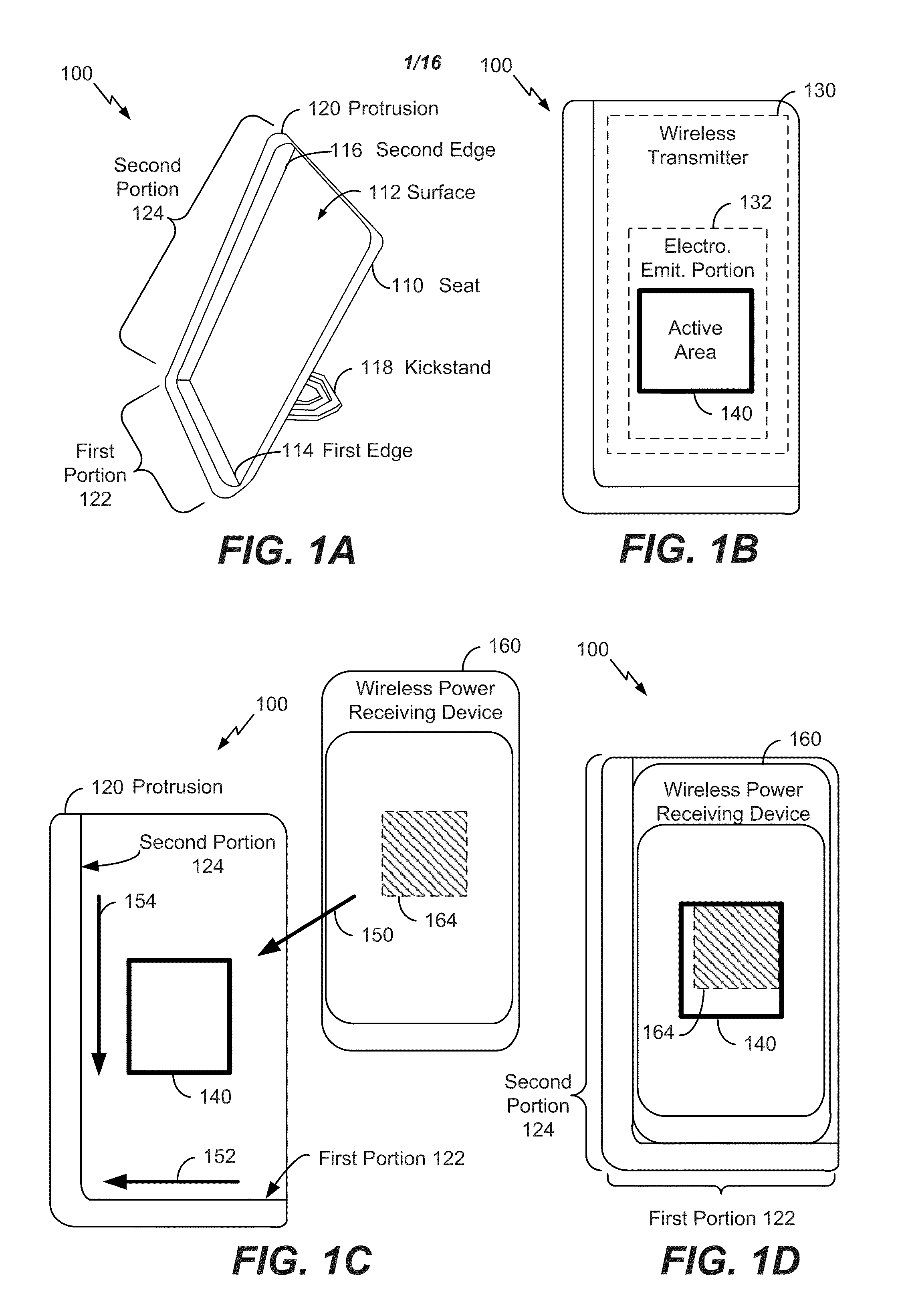
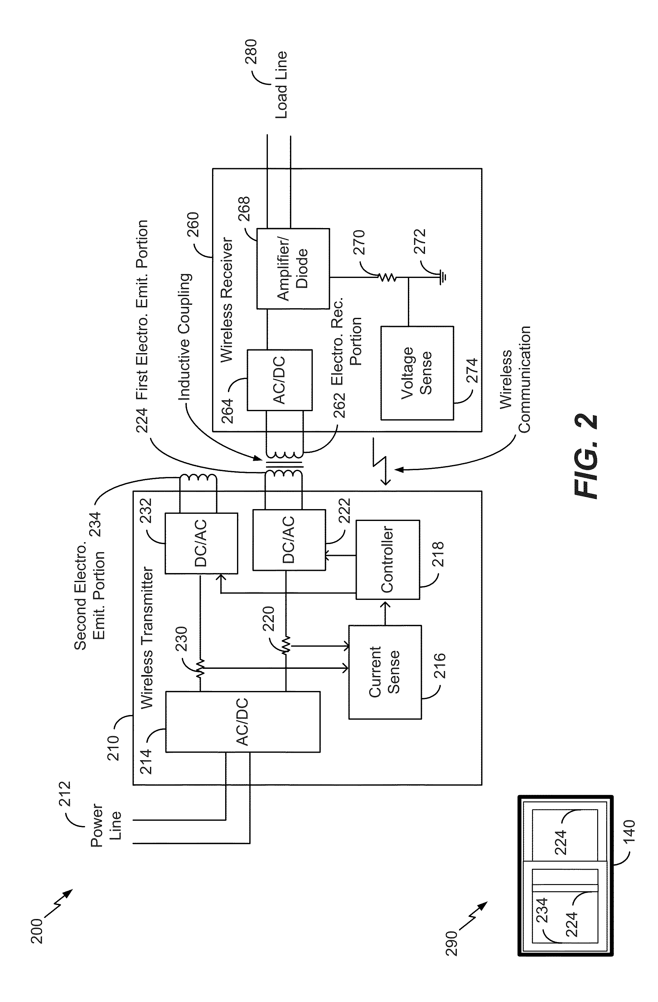
[0023]Referring to FIGS. 1A-D, multiple views of a wireless power transmitting device 100 are shown. The wireless power transmitting device 100 may be configured to wirelessly transfer power to at least one wireless power receiving device, such as a wireless power receiving device 160. The wireless power transmitting device 100 may also be configured to transfer power to different wireless power receiving device models of different receiving device types. For example, the wireless power receiving device 160 may include a mobile device, such as a mobile communication device or a tablet computer, a toothbrush, a game console controller, a global positioning system (GPS) device, a Bluetooth headset, another device configured to wirelessly receive power, or a combination thereof. ...


PUM

PropertyMeasurementUnit
angleaaaaaaaaaa
angleaaaaaaaaaa
angleaaaaaaaaaa

Abstract

A wireless charging device includes a wireless transmitter with an electromagnetic emitting portion. The wireless charging device also includes a seat having a surface and at least one protrusion from the surface. The seat accommodates at least one wireless power receiving device. The seat has an active area that contains the electromagnetic emitting portion. The at least one protrusion is configured as a guide for two sides of the at least one wireless power receiving device for placement over the active area. The placement of the at least one wireless power receiving device over the active area enables transferring of power to the at least one wireless power receiving device.

Description

CROSS-REFERENCE TO RELATED APPLICATIONS[0001]The present application claims priority to U.S. Provisional Application No. 61 / 863,081, filed Aug. 7, 2013, which application is hereby incorporated by reference herein in its entirety.FIELD OF THE DISCLOSURE[0002]The present disclosure is generally related to wireless power transmitting devices.BACKGROUND[0003]Charging pads are used to wirelessly transfer power from a transmitter of the charging pad to a receiver of a receiving device, such as a mobile phone or tablet computer. To transfer power from a charging pad to the receiving device, the receiving device may be placed on the charging pad by a user. Typically, an area of the charging pad is designated for placement of the receiving device. If the user does not correctly place the receiving device on the charging pad (e.g., does not align the receiving device with the designated area), power may be transferred at low efficiency or not at all. To account for misplacement (e.g., misali...

Claims


Application Information

Patent Timeline
Patent Type & Authority Applications(United States)
IPC IPC(8): H02J7/02H02J5/00H01F38/14H02J17/00
CPCH02J7/025H01F38/14H02J5/005H02J17/00H02J50/12H02J50/40H02J50/10
Inventor KOREN, DOTANZIV, ARANPETZINGER, JAMES
Owner SANDISK TECH LLC
Why Eureka
Try Eureka