Hazard warning system for vehicles

a technology for warning systems and vehicles, applied in traffic control systems, instruments, transportation and packaging, etc., can solve problems such as discrepancies in warnings to drivers, and achieve the effect of increasing the value or benefit of individual hazard warning systems

Inactive Publication Date: 2015-02-12
BCS BUSINESS CONSULTING SERVICES PTE
View PDF7 Cites 47 Cited by
  • Summary
  • Abstract
  • Description
  • Claims
  • Application Information

AI Technical Summary

Benefits of technology

[0014]The exemplary system also includes a first transmitter disposed in communication with the first detector and operable to broadcast a first remote warning signal subsequent to receiving the detector's first output. If the first vehicle experiences a sufficiently significant collision, the first remote warning signal is broadcast for reception by compatible hazard warning systems carried in nearby vehicles. The first remote warning signal may be transmitted from one vehicle directly to other vehicles, without passing through any intermediary. In some embodiments, the first remote warning signal may be transmitted to other vehicles via repeaters or amplifiers, such as repeaters mounted in satellites or in terrestrial infrastructure (e.g., towers, underpasses, buildings, etc.). One advantage of automatic, direct vehicle-to-vehicle communication is that warnings may be more immediate, and may be more effective at preventing additional collisions than conventional methods of warning of hazards. Furthermore, systems configured to communicate directly with other systems may be deployed without modifying infrastructure. Another benefit of the hazard warning systems disclosed herein is that warnings may be transmitted around curves or over hills, and may provide vehicle operators information regarding hazards beyond their immediate vision (which, when traveling at high speeds, may be a distance traveled in a relatively short period of time).
[0022]The exemplary system may be adapted for use in cooperation with at least a second hazard warning system. The second warning system is structured to be carried by a second vehicle to detect a collision involving the second vehicle and, consequently, broadcast a remote warning signal to warn occupants of nearby vehicles, such as the first vehicle. A plurality of hazard warning systems may be carried in a corresponding plurality of different vehicles. Desirably, such plurality of hazard warning systems are at least compatibly arranged to broadcast and receive mutually compatible remote warning signals. As more and more vehicles include hazard warning systems, the value or benefit of individual hazard warning systems may increase (i.e., hazard warning systems may have a demand-side economy of scale). In a best-case situation, every vehicle on the road would include a hazard warning system able both to communicate a remote warning to nearby vehicles, and operably receive such a remote warning. Consequently, a broadcast remote warning signal would provide a local warning to each nearby vehicle in range to receive the remote warning signal.

Problems solved by technology

The vehicles transmit their speed data to each other, and large speed discrepancies generate warnings to drivers.

Method used


Image

  • Hazard warning system for vehicles
  • Hazard warning system for vehicles
  • Hazard warning system for vehicles

Examples


second embodiment

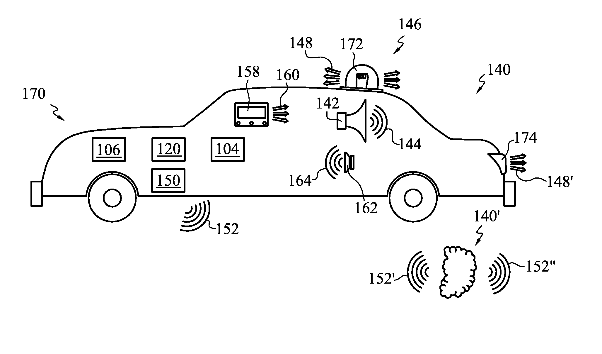
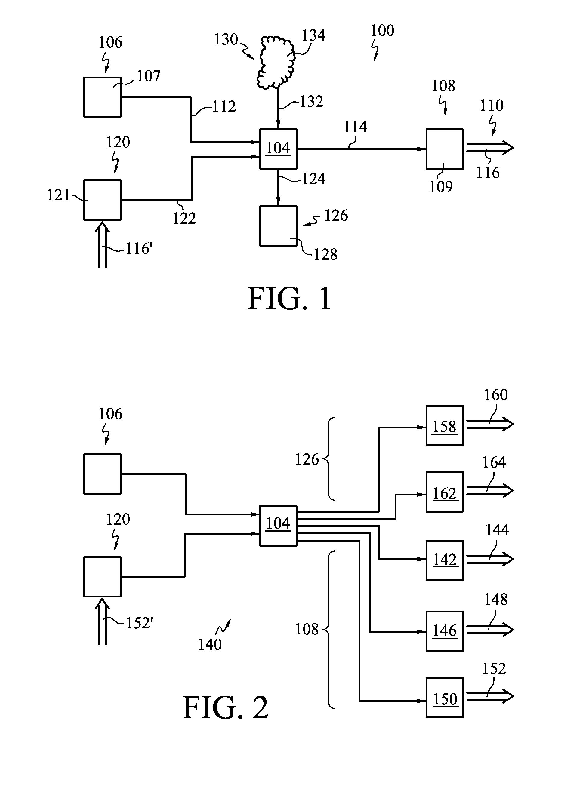
[0051]With reference now to FIG. 2, a second embodiment, generally indicated at 140, includes a detector 106 in communication through a controller 104 to operate a remote warning signal transmitter 108. As illustrated, a remote warning signal transmitter 108 may be embodied as one or more of: an alarm 142 operable to transmit a loud sonic signal 144 that is audibly perceptible to approaching traffic (e.g., a siren); a warning light 146 operable to transmit a warning signal 148 that is visibly perceptible to approaching traffic (e.g., a flashing light); and a transmitter 150 operable to transmit a remote warning signal 152 that may be received by a signal receiving apparatus 120 carried in an approaching vehicle.

embodiment 140

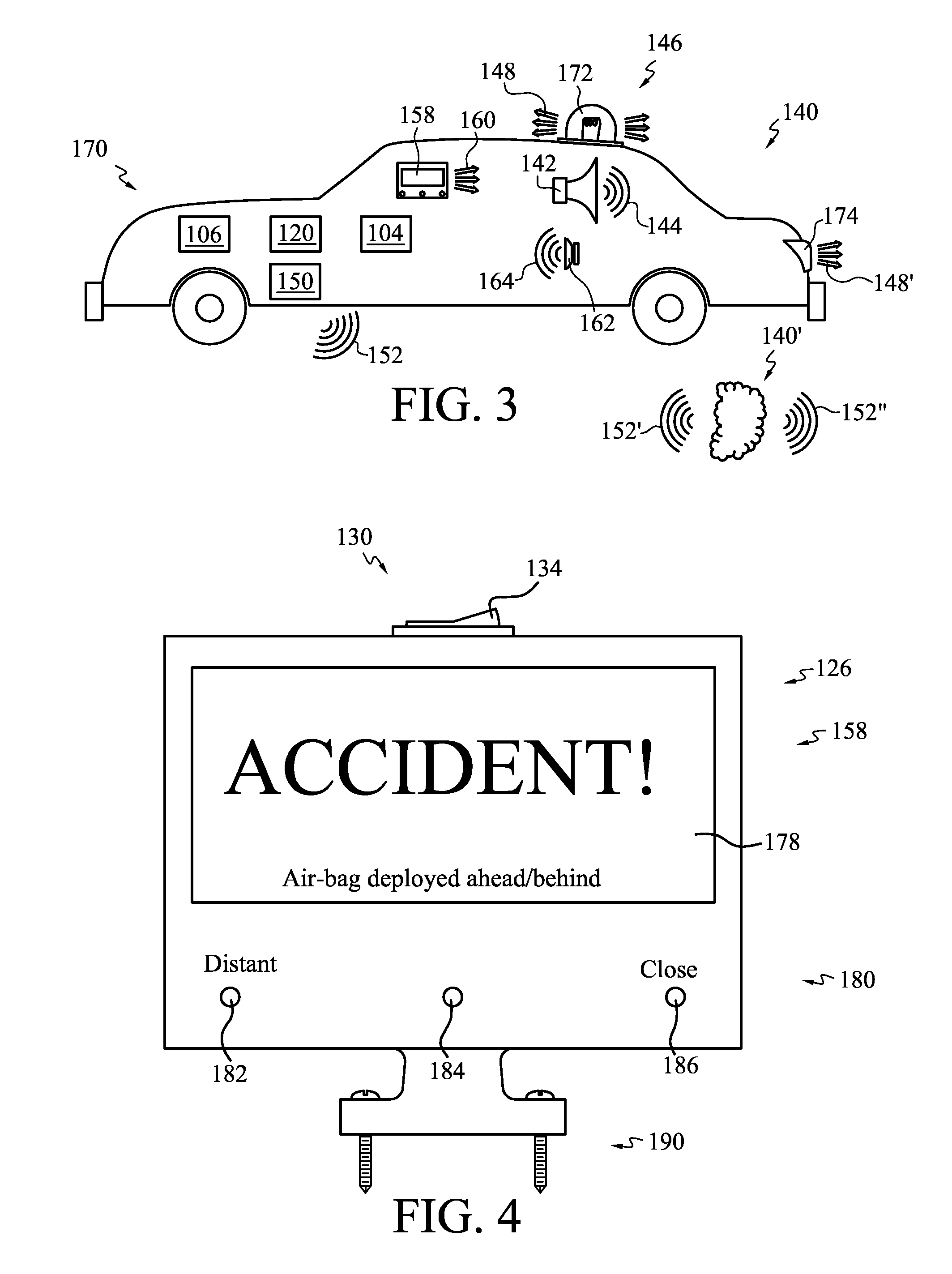
[0052]Embodiment 140 also includes a receiver 120 in communication through controller 104 to operate a local warning device 126. A local warning device 126 may include one or more of: a local display element 158 configured to transmit a local signal 160 that is visibly perceptible to an occupant of the vehicle; and a speaker 162 configured to produce a local sound output 164 that is audible to the occupant. Display elements 158 may include, for example, LED and LCD display panels, one or more light that can emit individually distinguishable colors, an array of lights, a bar graph, a meter with a rotating needle, and the like. An audible signal 164 may be used in combination with a visual signal 160 to increase the likelihood that the operator of the vehicle will notice and heed the warning. The audible signal 164 and / or the visual signal 160 may be configured to be different from other signals conveyed to the vehicle operator (e.g., a low-fuel light, an emissions-control system ligh...


PUM


Abstract

A system adapted to provide a warning to a vehicle operator of nearby hazards, e.g., that a nearby vehicle has been in a collision or is otherwise inoperable. Embodiments include a detector operable to detect a hazard, a transmitter to transmit a warning signal, a receiver to receive a transmitted warning signal, and a display to warn the operator of an approaching vehicle of the hazard. Some embodiments incorporate feedback from a vehicle's airbag deployment circuitry to provide a trigger effective to broadcast the warning signal. The operator of an approaching vehicle may be provided with a visual and / or an audible warning signal, e.g., via a cellular telephone. Certain embodiments provide such warning to approaching vehicles via the transmitted warning signal and a display and / or speaker carried in the approaching vehicle. Audible and visual warnings may be transmitted directly from the crashed vehicle.

Description

CROSS-REFERENCE TO RELATED APPLICATIONS[0001]This application is a continuation of co-pending U.S. patent application Ser. No. 13 / 883,512, filed May 3, 2013, now U.S. Pat. No. 8,884,780, issued Nov. 11, 2014, which application is a national phase entry under 35 U.S.C. §371 of International Patent Application PCT / US2011 / 001837, filed Oct. 30, 2011, designating the United States of America and published in English as International Patent Publication WO 2012 / 071054 on Jul. 26, 2012, which claims the benefit under Article 8 of the Patent Cooperation Treaty and under 35 U.S.C. §119(e) to U.S. patent application Ser. No. 12 / 927,841, filed Nov. 24, 2010, now U.S. Pat. No. 8,552,886, issued Oct. 8, 2013, for “Crash Warning System for Motor Vehicles,” the disclosure of each of which is hereby incorporated herein in its entirety by this reference.TECHNICAL FIELD[0002]The application relates to warning devices. Preferred embodiments are adapted to detect occurrence of a hazard, such as a colli...

Claims


Application Information

Patent Timeline
Patent Type & Authority Applications(United States)
IPC IPC(8): B60Q5/00B60Q1/52G08G1/0967G08G1/16G08G1/00
CPCB60Q5/006G08G1/162B60Q1/52G08G1/096741G08G1/096791G08G1/205B60Q9/008
Inventor BURNISON, CHANTALBENSOUSSAN, PHILIPPE
Owner BCS BUSINESS CONSULTING SERVICES PTE
Why Eureka
Try Eureka