
Bonding structure of electronic equipment

a technology of electronic equipment and bonding structure, which is applied in the direction of identification means, sustainable manufacturing/processing, semiconductor/solid-state device details, etc., can solve the problems of electrical resistance increase and electronic equipment defects may be generated, and achieve the effect of maintaining mechanical reliability

Active Publication Date: 2015-02-12
ELECTRONICS & TELECOMM RES INST
View PDF4 Cites 19 Cited by
  • Summary
  • Abstract
  • Description
  • Claims
  • Application Information

AI Technical Summary

Benefits of technology

The patent text describes an improved way of bonding together electronic equipment that includes a flexible display. This method increases the reliability and flexibility of the bonding, which allows for greater performance and durability of the equipment.

Problems solved by technology

In this case, electrical resistance may increase, and defects of the electronic equipments may be generated.

Method used


Image

  • Bonding structure of electronic equipment
  • Bonding structure of electronic equipment
  • Bonding structure of electronic equipment

Examples


Embodiment Construction

[0034]The advantages and the features of the inventive concept, and methods for attaining them will be described in example embodiments below with reference to the accompanying drawings. The inventive concept may, however, be embodied in different forms and should not be construed as limited to the embodiments set forth herein. Rather, these embodiments are provided so that this description will be thorough and complete, and will fully convey the scope of the present inventive concept to those skilled in the art.

[0035]The terminology used herein is for the purpose of describing particular example embodiments only and is not intended to limit the present inventive concept. As used herein, the singular forms are intended to include the plural forms as well, unless the context clearly indicates otherwise. It will be further understood that the terms “comprises” and / or “comprising,” when used in this specification, specify the presence of stated features, steps, operations, and / or devic...


PUM


Abstract

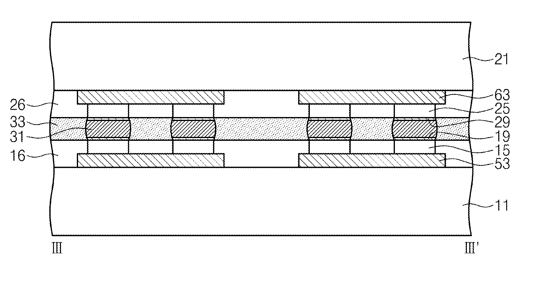
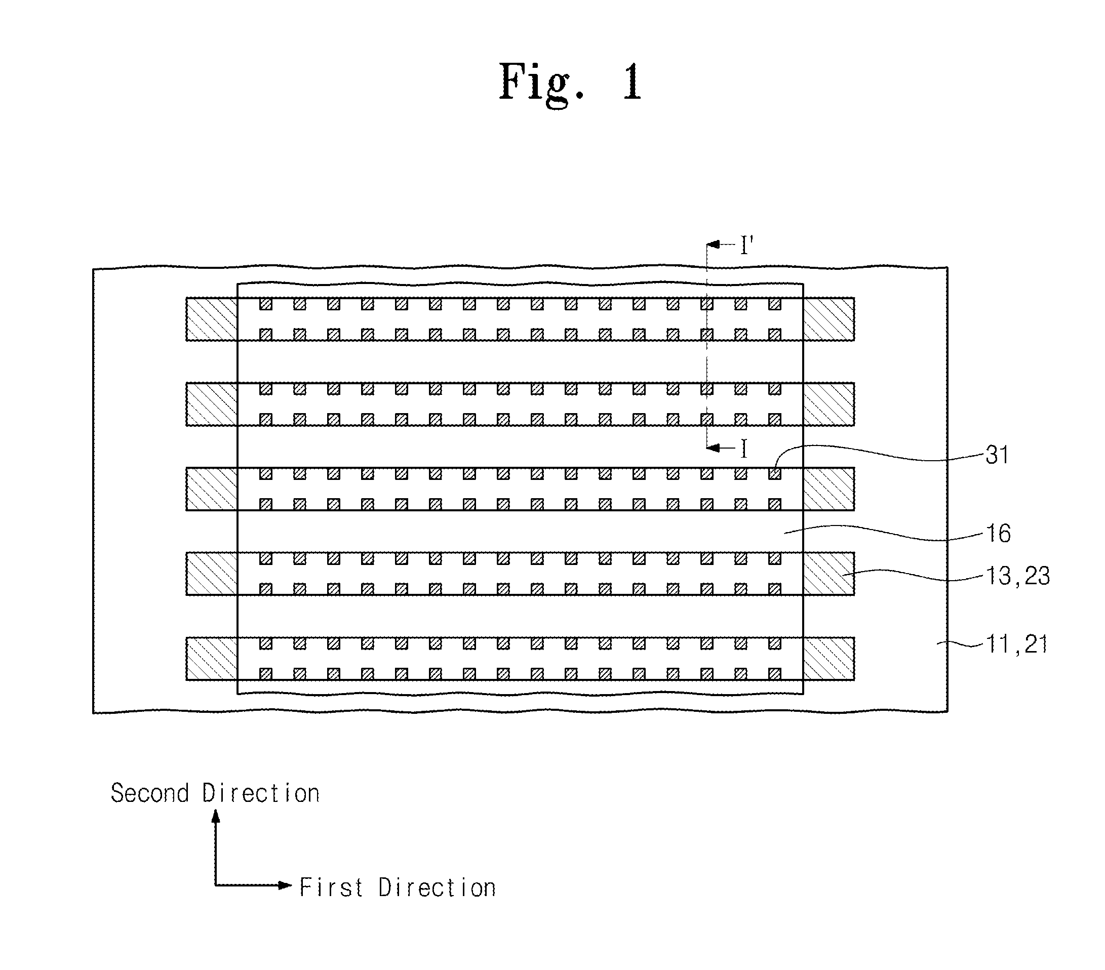
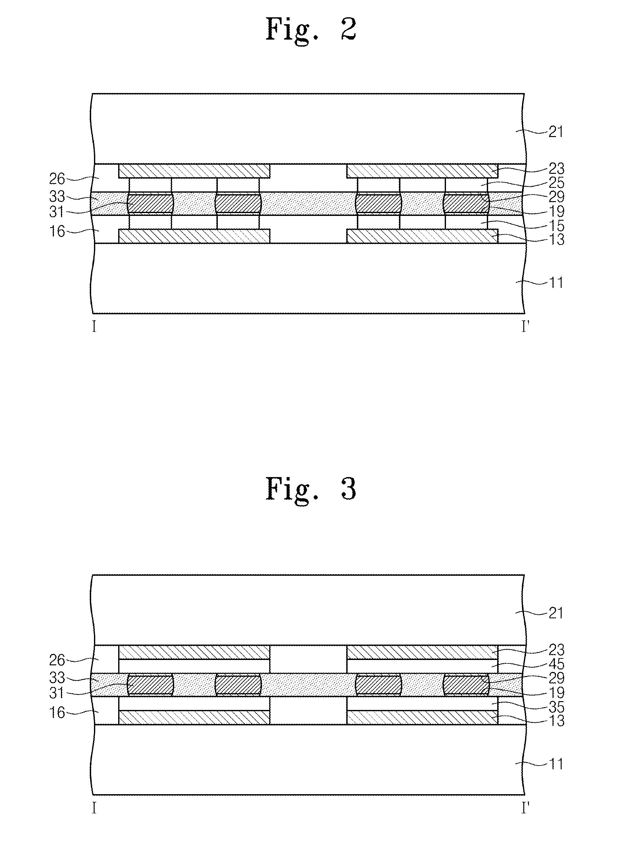
Provided is a bonding structure of an electronic equipment including first electrodes extended in a first direction and arranged in a second direction on a stretchable display panel having stretchability, second electrodes extended in a first direction and arranged in a second direction on a substrate and facing the first electrodes, and solder bonding parts interposed between the first electrodes and the second electrodes, facing each other in the second direction, and constituting a plurality of rows in the first direction.

Description

CROSS-REFERENCE TO RELATED APPLICATIONS[0001]This U.S. non-provisional patent application claims priority under 35 U.S.C. §119 of Korean Patent Application No. 10-2013-0094914, filed on Aug. 9, 2013, the entire contents of which are hereby incorporated by reference.BACKGROUND OF THE INVENTION[0002]The present disclosed herein relates to a bonding structure of an electronic equipment, and more particularly, to a bonding structure of an electronic equipment including a stretchable display.[0003]Recently, a electronic equipment has a general constitution of connecting an stretchable display with an electronic circuit module installed on a rigid substrate. To connect the stretchable display and the circuit of the rigid substrate, a connection method using an anisotropic conductive film (ACF) is known.[0004]The ACF has a dispersed state of conductive particles into a polymer. The ACF is disposed between the stretchable display and the rigid substrate for connection, and heat and pressure...

Claims


Application Information

Patent Timeline
Patent Type & Authority Applications(United States)
IPC IPC(8): H05K1/11
CPCH05K1/111H01L2924/0002H05K1/0283H05K1/189H05K3/3436H05K2201/10128H05K2201/10734Y02P70/50H01L2924/00G09F9/00H01L23/48
Inventor CHOI, KWANG-SEONGBAE, HYUN-CHEOLLEE, HAKSUNEOM, YONG SUNG
Owner ELECTRONICS & TELECOMM RES INST
Learn More