
Electrical connector having an EMI absorber

Active Publication Date: 2015-02-12
TYCO ELECTRONICS LOGISTICS AG (CH)
View PDF11 Cites 20 Cited by
  • Summary
  • Abstract
  • Description
  • Claims
  • Application Information

AI Technical Summary

Benefits of technology

The patent describes an electrical connector that can be used to connect cables with a conductive shield. The connector has a housing with an electrically conductive shield and holds an electrical contact. The cable end has a channel that holds the end segment of the cable and is connected to the housing. The connector also contains an electromagnetic interference (EMI) absorber to absorb any EMI emitted from the cable. The technical effect of this connector is to provide effective protection against EMI interference and to ensure reliable electrical connection.

Problems solved by technology

EMI emitted from the cable assembly may harm the signal integrity and / or electrical performance of neighboring electrical devices, for example.
The EMI shielding of at least some known cable assemblies may be inadequate because of the increasing signal speeds being transmitted through cable assemblies.
For example, the connection between the housing shield and the cable shield may leak EMI above certain signal speeds, such as above approximately 10 gigahertz (GHz).
Some known cable assemblies wherein the cable shield is a cable braid that is dressed over a ferrule of the housing may be especially susceptible to EMI leakage at the interface between the cable braid and the ferrule because of the flare of the cable braid over the ferrule.

Method used


Image

  • Electrical connector having an EMI absorber
  • Electrical connector having an EMI absorber
  • Electrical connector having an EMI absorber

Examples


Embodiment Construction

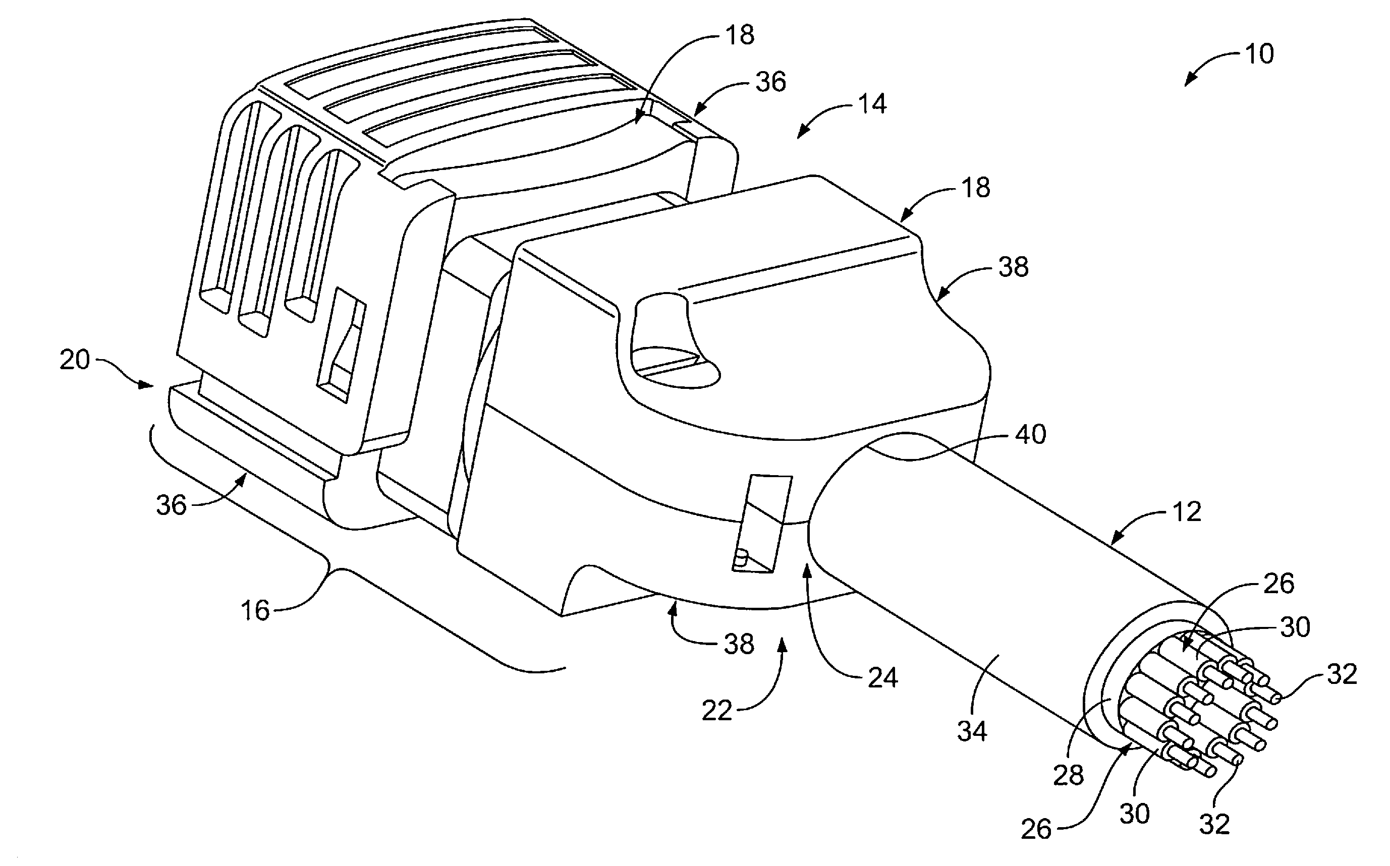
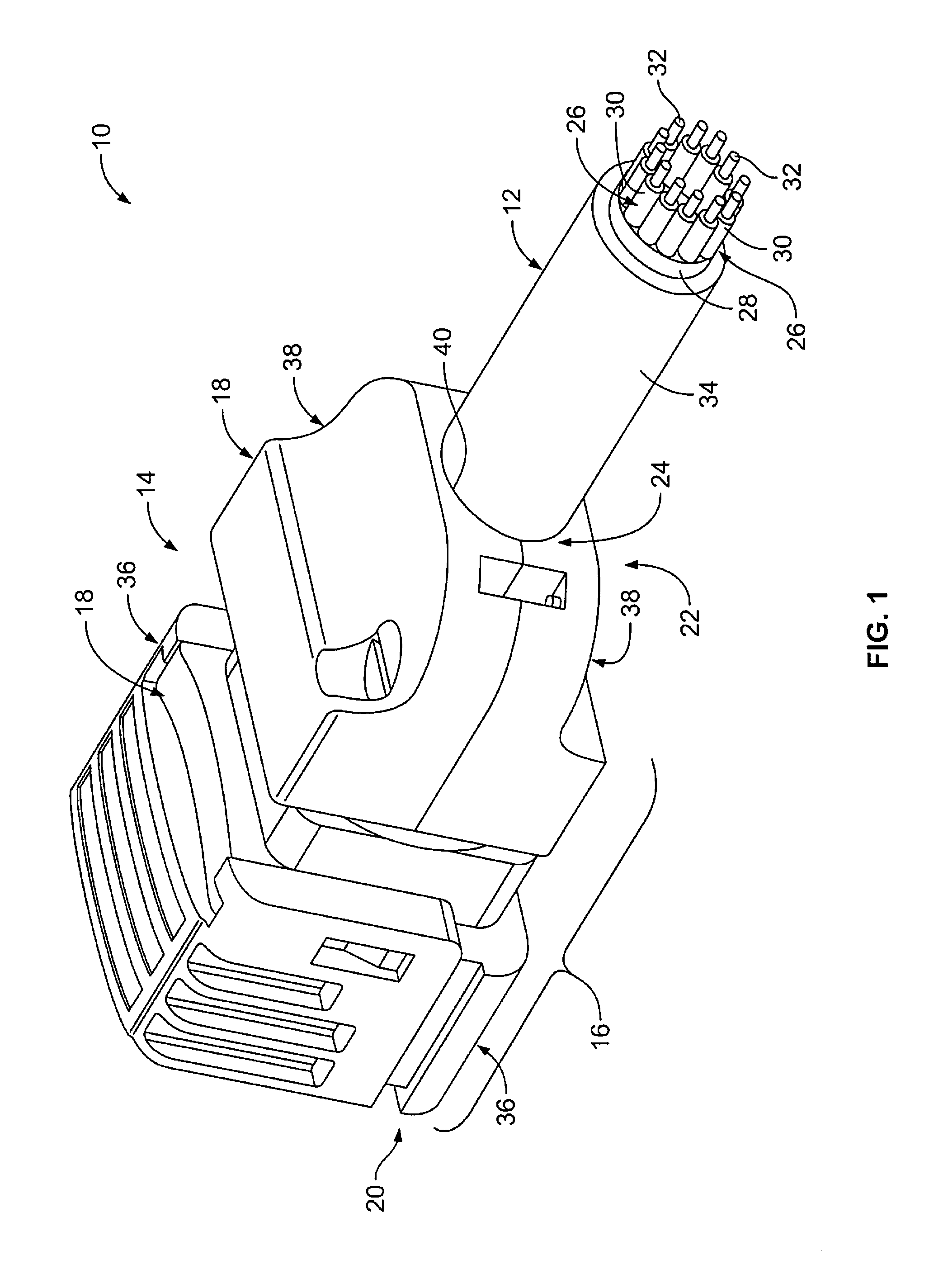
[0013]FIG. 1 is a perspective view of an embodiment of a cable assembly 10. The cable assembly includes a cable 12 and an electrical connector 14 that terminates the cable 12. In the illustrated embodiment, the electrical connector 14 is a shielded radio frequency (RF) connector, however the electrical connector 14 may be any other type of electrical connector. Optionally, the electrical connector 14 is a relatively high data rate connector. For example, in some embodiments, the electrical connector 14 is configured to transmit high-speed data signals, such as, but not limited to, data signals greater than approximately 5 gigabit per second (Gb / s), data signals greater than approximately 10 Gb / s, data signals greater than approximately 15 Gb / s, or data signals greater than approximately 20 Gb / s. The electrical connector 10 may be used for any application and is optionally adapted for use in military applications, aerospace applications, automotive applications, industrial applicatio...


PUM


Abstract

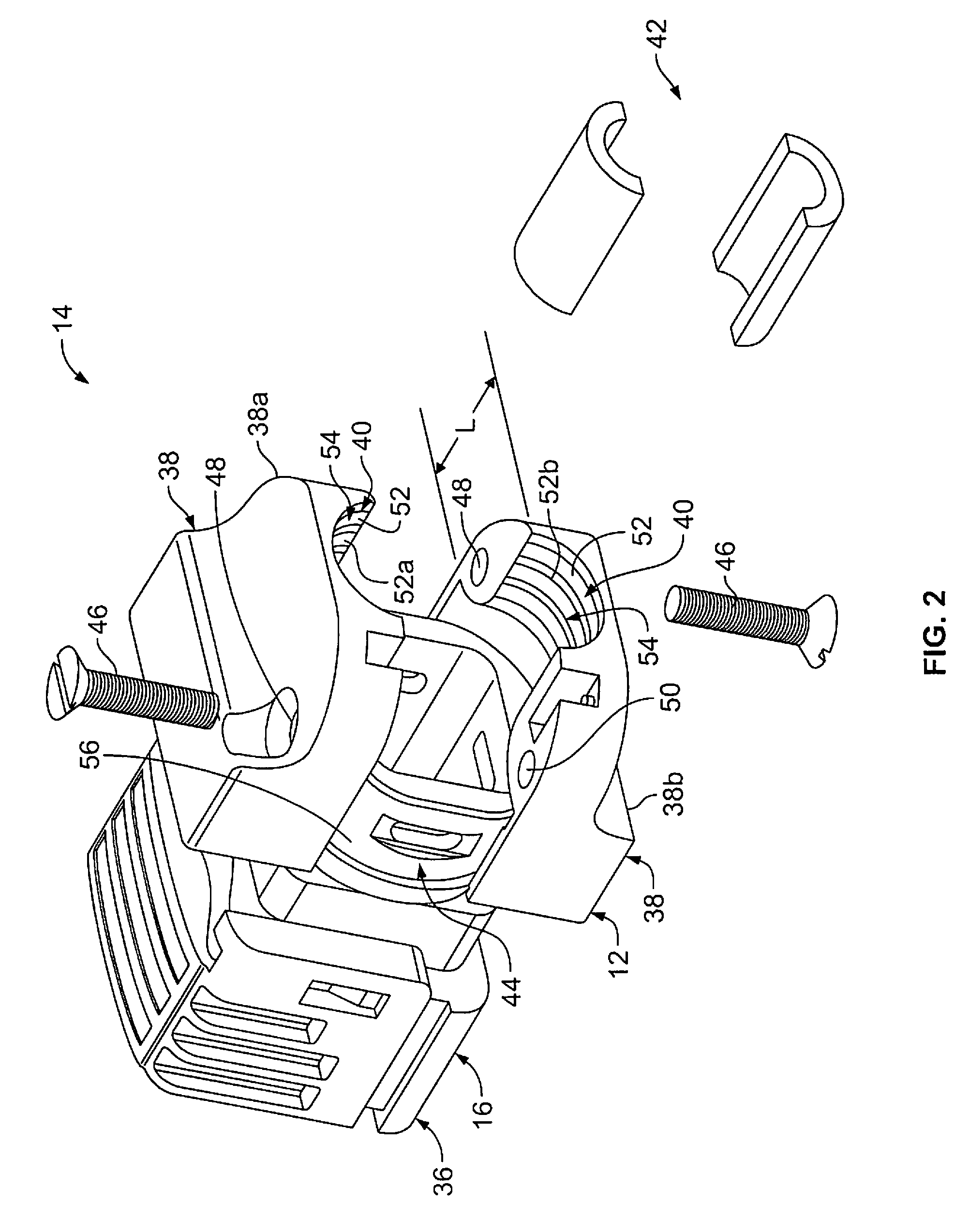
An electrical connector is provided for terminating a cable having a cable shield. The electrical connector includes an electrical contact configured to be terminated to an end of a wire of the cable, and a housing having a body that extends from a mating end to a cable end. The housing includes a connector shield. The electrical contact is held by the housing. The cable end includes a cable channel that is configured to hold an end segment of the cable therein such that the cable shield is electrically engaged with the connector shield. An electromagnetic interference (EMI) absorber is held within the cable channel such that the EMI absorber is configured to extend around the cable shield along at least a portion of a length of the cable channel. The EMI absorber is configured to absorb EMI emitted from the cable.

Description

BACKGROUND OF THE INVENTION[0001]The subject matter herein relates generally to an electrical connector for terminating an electrical cable having a cable shield.[0002]Electrical connectors that terminate electrical cables may include a housing that provides shielding for one or more electrical contacts held by the housing. For example, the housing may include an electrically conductive coating (e.g., a plating), an electrically conductive shell, and / or another electrically conductive structure that extends around the electrical contacts for shielding the electrical contacts. The shield of the housing is terminated to a shield (e.g., a cable braid) of the cable that provides shielding for one or more electrical wires of the cable. The shielding provided by the housing shield and the cable shield may reduce electromagnetic interference (EMI) emissions from the cable assembly of the electrical cable and the electrical connector. EMI emitted from the cable assembly may harm the signal ...

Claims


Application Information

Patent Timeline
IPC IPC(8): H01R13/6581
CPCH01R13/6581H01R13/65914H01R13/6593H01R13/6599H01R13/7193H05K9/0018
Inventor DUNWOODY, STEVEN DAVIDLONG, RICHARD JAMES
Owner TYCO ELECTRONICS LOGISTICS AG (CH)
Learn More