Method for determining a brake pressure value on the basis of characteristic curves

a technology of characteristic curves and brake pressure values, applied in the direction of braking systems, process and machine control, instruments, etc., can solve the problems of inability to keep the respective wheel in the optimum slip range, adverse effects on braking power or stability during braking, and inability to accurately control

Active Publication Date: 2015-02-12
KNORR-BREMSE SYST FUER NUTZFAHRZEUGE GMBH
View PDF15 Cites 9 Cited by
  • Summary
  • Abstract
  • Description
  • Claims
  • Application Information

AI Technical Summary

Benefits of technology

[0022]According to one development of the method according to the invention, the first characteristic curve and/or the second characteristic curve are also determined or adapted as a function of aging-induced and/or wear-induced parameters such as the number of activations of the fo

Problems solved by technology

If the pressure requirements are implemented imprecisely, the ABS closed-loop control arrangement cannot keep the respective wheel in the optimum slip range.
As a result, adverse effects incur on the braking power or stability during braking.
However, for the sake of cost-effective fabrication of the brake control system it is often the case that no wheel pressure sensors are present with the result that the current wheel pressure which is necessary for the closed-loop control arrangement has to be determined by a wheel pressure model.
On the basis of the limited supply pressure in the reservoir containers and the relatively long pneumatic piping, in particular in utility vehicles, such ABS closed-loop control is possible without information about the admission pressure at the ABS control valve 8, but when the admission pressure information is dispensed with the ABS closed-loop contr

Method used


Image

  • Method for determining a brake pressure value on the basis of characteristic curves
  • Method for determining a brake pressure value on the basis of characteristic curves
  • Method for determining a brake pressure value on the basis of characteristic curves

Examples


Embodiment Construction

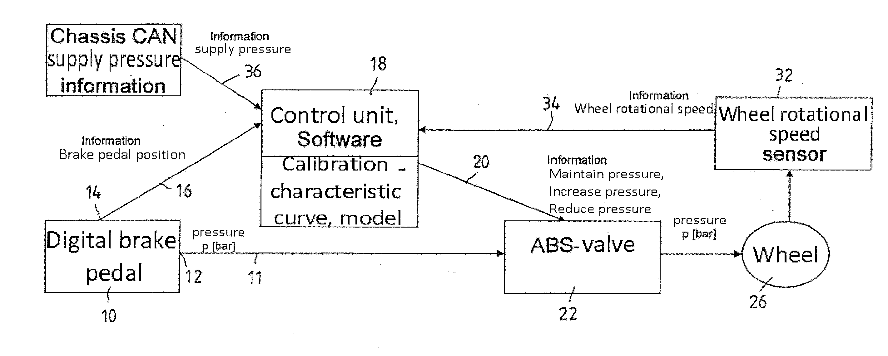
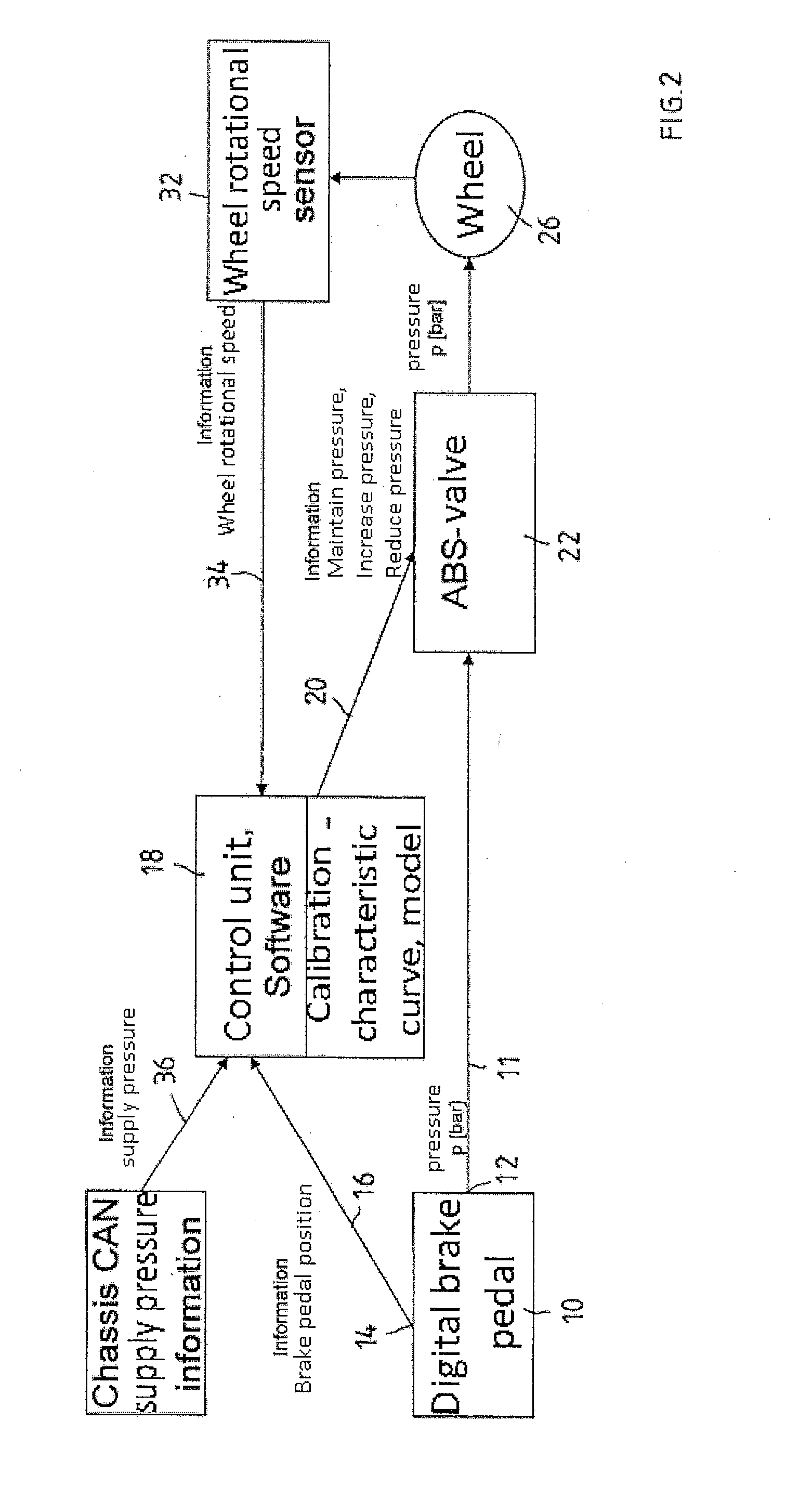
[0033]Part of a electro-pneumatic brake system of a utility vehicle is illustrated in FIG. 2 and has an electro-pneumatic braking value encoder 10, for example an electronic foot-operated brake module with at least one pneumatic channel 12 via which brake pressure values can be applied to a pneumatic brake circuit of the braking device, which brake pressure values are formed as a function of the degree of activation of a foot-operated brake pedal of the foot-operated brake module 10. For this purpose, the pneumatic channel 12 of the foot-operated brake module 10 includes, for example, a service brake valve (not shown explicitly here) which generates pneumatic control pressures or brake pressures as a function of the activation of a foot-operated brake pedal of the foot-operated brake module and applies them to a pneumatic line 11 which connects the pneumatic channel 12 to an ABS control valve 22.

[0034]Furthermore, the foot-operated brake module 10 has at least one electrical channel...


PUM


Abstract

A method for determining a value of a brake pressure modulated by a pneumatic channel of a braking value encoder having at least one electrical channel, in a braking device of a vehicle, including: (a) a first characteristic curve, in which the dependence of the signals, modulated by the at least one electrical sensor, on the degree of activation of the braking value encoder is represented, is determined and stored; (b) a second characteristic curve, in which the dependence of the brake pressure values, modulated by the channel, on the electrical signals detected by the sensor is represented, is determined and stored; and (c) the brake pressure value corresponding to a specific braking request as a result of activation of the encoder is determined based on the first and second characteristic curves.

Description

FIELD OF THE INVENTION[0001]The present invention relates to a method for determining the brake pressure value of the brake pressure which is modulated by a pneumatic channel of a braking value encoder further having at least one electrical channel, in a brake system of a motor vehicle without using a brake pressure sensor, wherein electrical signals which represent brake pressure values which are desired as a function of activations of the braking value encoder are generated by at least one electrical sensor which is assigned to the electrical channel, and to a braking device of a vehicle in which a brake pressure value which is determined according to the method is used.BACKGROUND INFORMATION[0002]German patent document DE 198 52 399 A1 discusses a braking value encoder, which can be activated by a foot-operated brake pedal, for an electronic brake system, which braking value encoder generates a pneumatic brake pressure in a pneumatic channel as a function of the activation, and a...

Claims


Application Information

Patent Timeline
IPC IPC(8): B60T17/22B60T8/176B60T8/17
CPCB60T17/22B60T8/176B60T8/17B60T7/042B60T13/662B60T2270/14B60T8/327B60T8/36B60T8/172
Inventor SCHREITER, MARKUS
Owner KNORR-BREMSE SYST FUER NUTZFAHRZEUGE GMBH
Why Eureka
Try Eureka