
Heat cycle for transfer of heat between media and for generation of electricity

a technology of heat transfer and heat cycle, which is applied in the direction of refrigeration devices, lighting and heating apparatus, compression machines with several evaporators, etc., can solve the problems of difficulty in reaching further, and the technology has reached a limit that is difficult to exceed

Active Publication Date: 2015-02-19
NODITECH AB
View PDF1 Cites 5 Cited by
  • Summary
  • Abstract
  • Description
  • Claims
  • Application Information

AI Technical Summary

Benefits of technology

The invention is a converting unit that allows for better use of a surplus of pressure and heat in a heat pump circuit, leading to improved efficiency and reduced energy consumption. Additionally, the invention helps improve the environment by reducing the amount of electrical energy required for a certain energy output. Its potential applications range from cooling to heating, regardless of the power range.

Problems solved by technology

However, it has proved that it is difficult to reach further, since the technology has already been sophisticated to attain the high COP values mentioned above, among other things by introducing high-efficiency plate heat exchangers, low-energy centrifugal pumps, more energy-efficient scroll compressors and optimized refrigerant mixtures (i.e. the working fluids that complete the cycle in a heat pump cycle).
Thus, it seems as if the technology has reached a limit that is difficult to exceed, other than by possibly increasing the coefficient of performance by tenths, when using conventional instruments.
However, it is very difficult to cause a turbine to function under the premises that prevail under the conditions that occur in the working fluid between the condenser and the evaporator.
A plurality of heat exchangers and pumps render the device complicated.

Method used


Image

  • Heat cycle for transfer of heat between media and for generation of electricity
  • Heat cycle for transfer of heat between media and for generation of electricity
  • Heat cycle for transfer of heat between media and for generation of electricity

Examples


Embodiment Construction

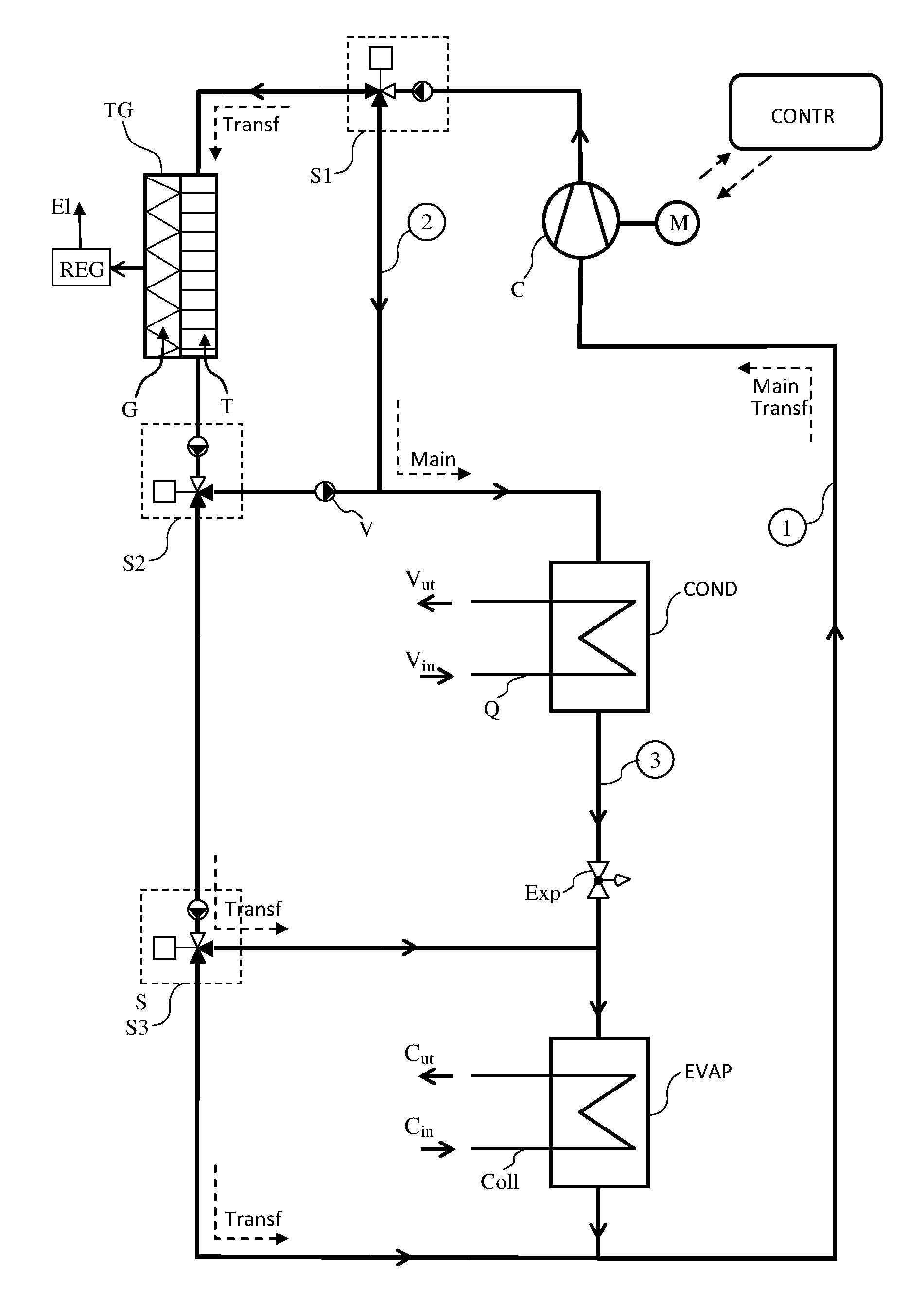
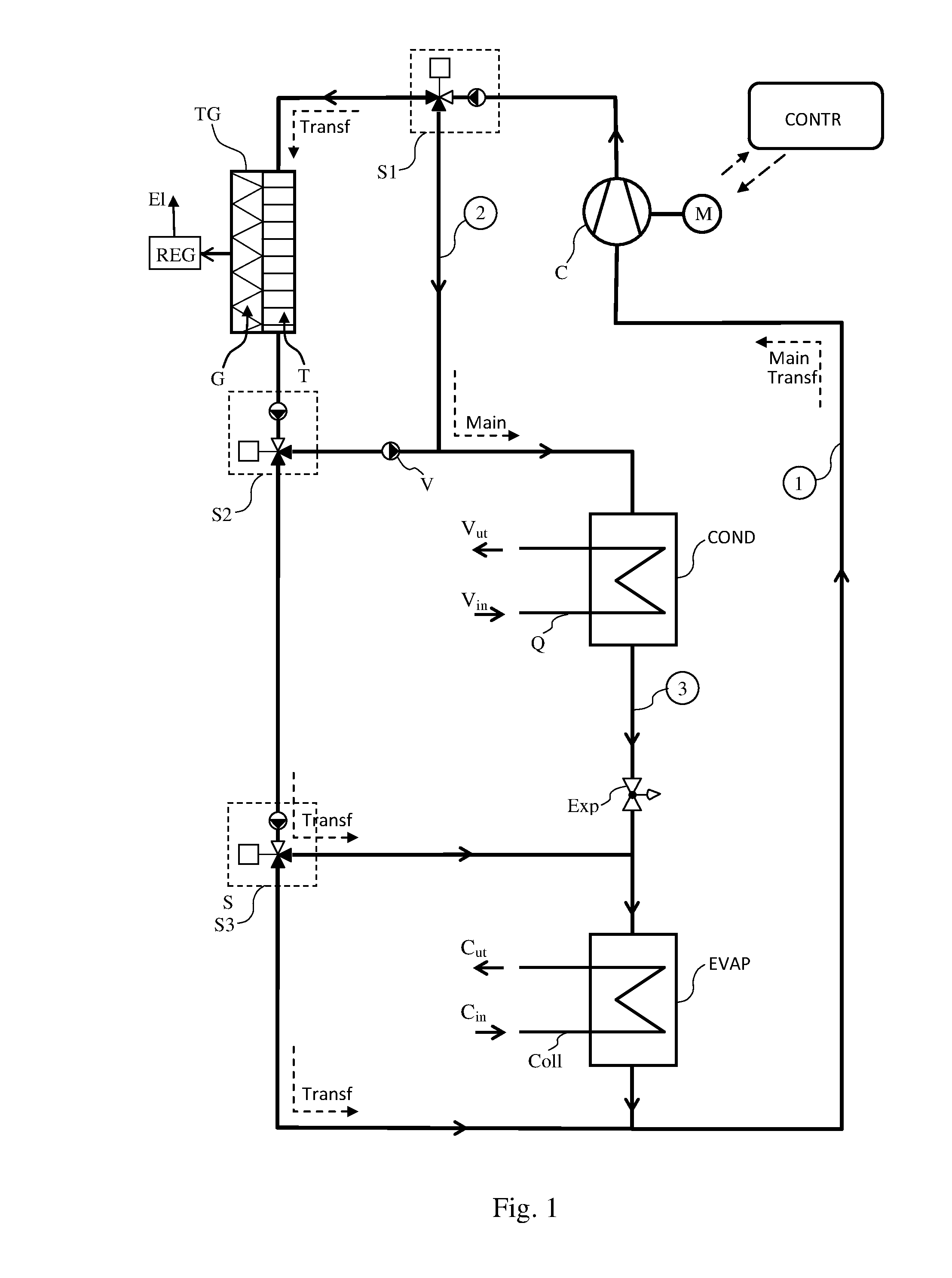
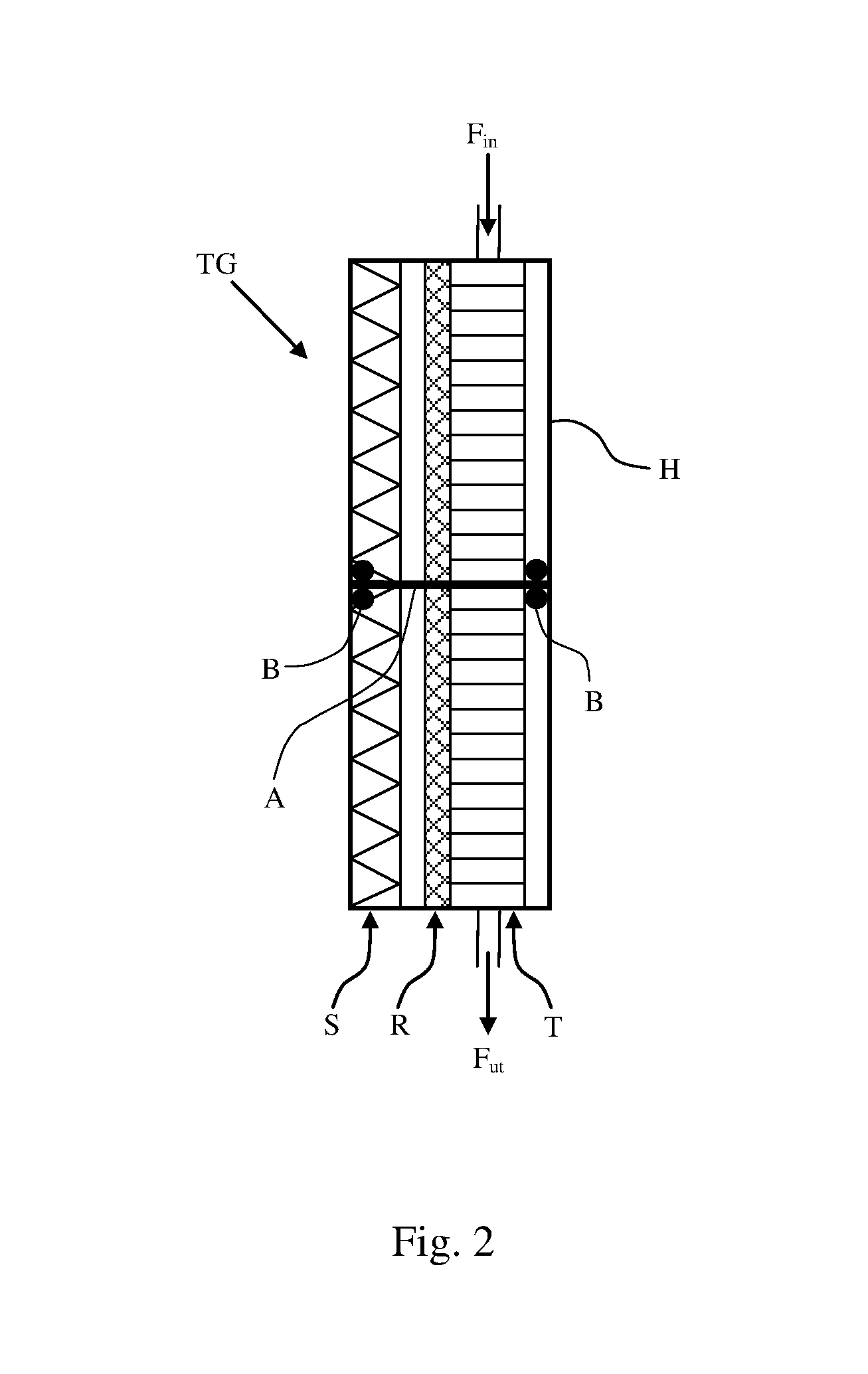
[0017]The present invention constitutes a modification of a heat pump circuit according to the prior art. To this end, the primary aim has been to arrange the heat pump circuit, with certain means, such that more heat is absorbed from the collector circuit in a plant with a predetermined heating / cooling requirement. To achieve this, the electric motor is adapted to deliver more power to a compressor that is overdimensioned in relation to what is required to produce the necessary power to the heat circuit in the condenser or, in the case of cooing machines, the necessarily extracted power in the evaporator. By this measure, in case of a certain coefficient of performance, additional energy will be supplied to the working fluid in the heat pump circuit. This additionally supplied energy to the heat cycle cannot be delivered at the condenser since the heat cycle is designed for said required power. Instead, a bypass of the condenser is arranged from the outlet of the compressor via an ...


PUM


Abstract

A heat pump circuit including a compressor that compresses a working fluid from a gas in a low pressure, low temperature first state to a high pressure, a high temperature second state. A first subflow of the working fluid is condensed into a gaseous / liquid mixture and assumes a third state by the working fluid delivering heat to a first medium. The first subflow of the working fluid is expanded and returns to a gas in the first state by absorbing heat from a second medium, whereupon the working fluid completes the cycle again. A second subflow of the compressed working fluid is expanded from the second state and the energy contents in the second subflow converted into electrical energy, whereafter the expanded working fluid is returned to the compressor after passage of the evaporator, or after expansion in the energy converter from the second to the first state.

Description

TECHNICAL FIELD[0001]The present invention relates to a system that utilizes a heat cycle in which heat is transferred between a working fluid from a region with a low temperature to a region with a higher temperature. Depending on whether it is the lower or the higher temperature that is desired, devices with such a cycle are designated cooling device or heat pump, respectively.PRIOR ART[0002]Refrigeration technology has been developed for a long time and is utilized in refrigeration plants, air conditioning systems and, recently, also fully developed in the reverse process, in so-called heat pumps for heating, for example, dwellings. The use of the concept heat pump may be looked upon as an “alias” for a refrigeration plant when a heat cycle is used for the purpose of cooling an area. Thus, the concept of heat pump will be used in the following to designate the device that uses a heat cycle for heating and cooling, respectively.[0003]In a heat pump, a fluid operates which cyclical...

Claims


Application Information

Patent Timeline
IPC IPC(8): F25B49/02F25B41/06F25B41/04F25B29/00F25B31/02
CPCF25B49/025F25B29/003F25B31/02F25B2600/2501F25B41/062F25B2400/14F25B2600/024F25B41/043F01K25/08F25B11/00F25B25/005F25B2339/047F25B2400/0403F25B2400/0409F25B2400/0411F25B11/02F25B30/02
Inventor HOLLINGWORTH, HARDY
Owner NODITECH AB
Learn More