
Gear

a gear and gear technology, applied in the field of gearboxes, can solve the problems of low anti-shock capability, high accuracy and high sensitivity, increased vibrational friction and noise of the gear train, etc., and achieve the effect of reducing the rigidity of the gear spoke, the noise of the gear and the vibration of the gear

Inactive Publication Date: 2015-02-19
JOHNSON ELECTRIC SA
View PDF71 Cites 10 Cited by
  • Summary
  • Abstract
  • Description
  • Claims
  • Application Information

AI Technical Summary

Benefits of technology

The present invention is a gear with a simplified structure that can improve performance and reduce cost. It does this by making the gear spoke less rigid, reducing noise and vibration.

Problems solved by technology

However, the gear without a rubber cushion has a low anti-shock capability, high accuracy and high sensitivity, which results in increased vibrational friction and noise of the gear train during operation and thus an accelerated wear on the gears.
On the other hand, while the gear with a rubber cushion can address the above problems, it has a complicated structure and a large number of parts.
In addition, the gear with a rubber cushion has a problem of uneven rigidity when operating in a dual direction mode.

Method used


Image

  • Gear
  • Gear
  • Gear

Examples


Embodiment Construction

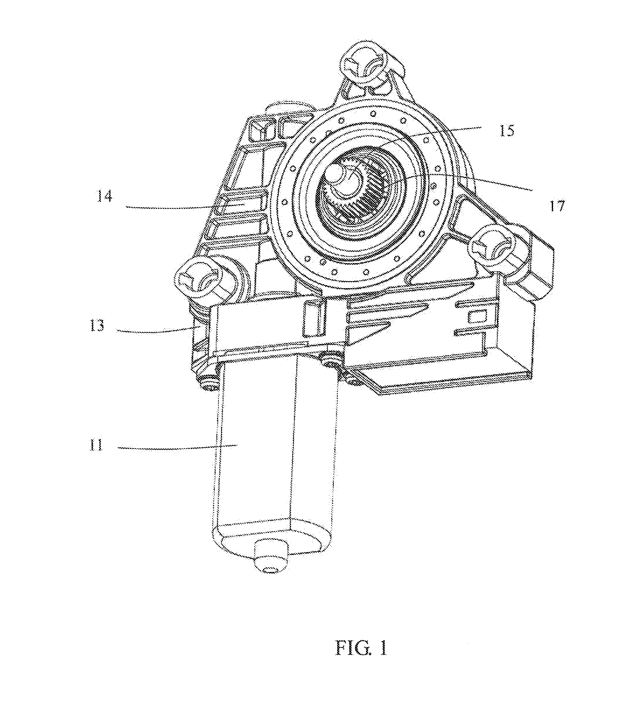
[0036]As shown in FIG. 1, a motor assembly for a vehicle window lift in accordance with a preferred embodiment of the present invention, includes a motor 11 and a gear box 13. The gear box 13 includes a housing 14, a stationary shaft 15 mounted to the outer housing 14, and a gear train including an output gear 17 rotatably mounted to the stationary shaft 15. A worm (not shown) is mounted on an output shaft of the motor 11 for driving the output gear 17, by means of which the rotational speed of the output is reduced.

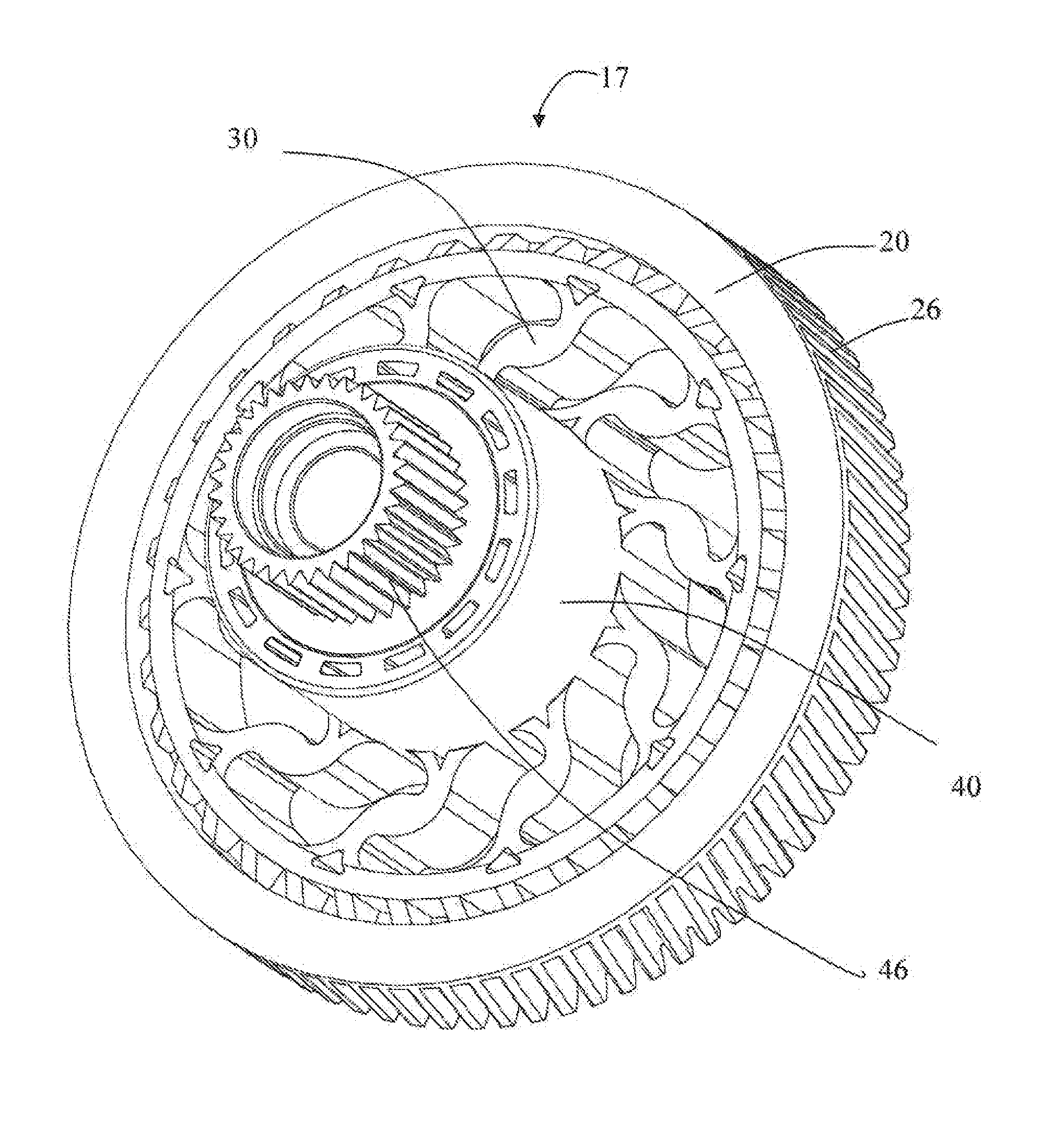
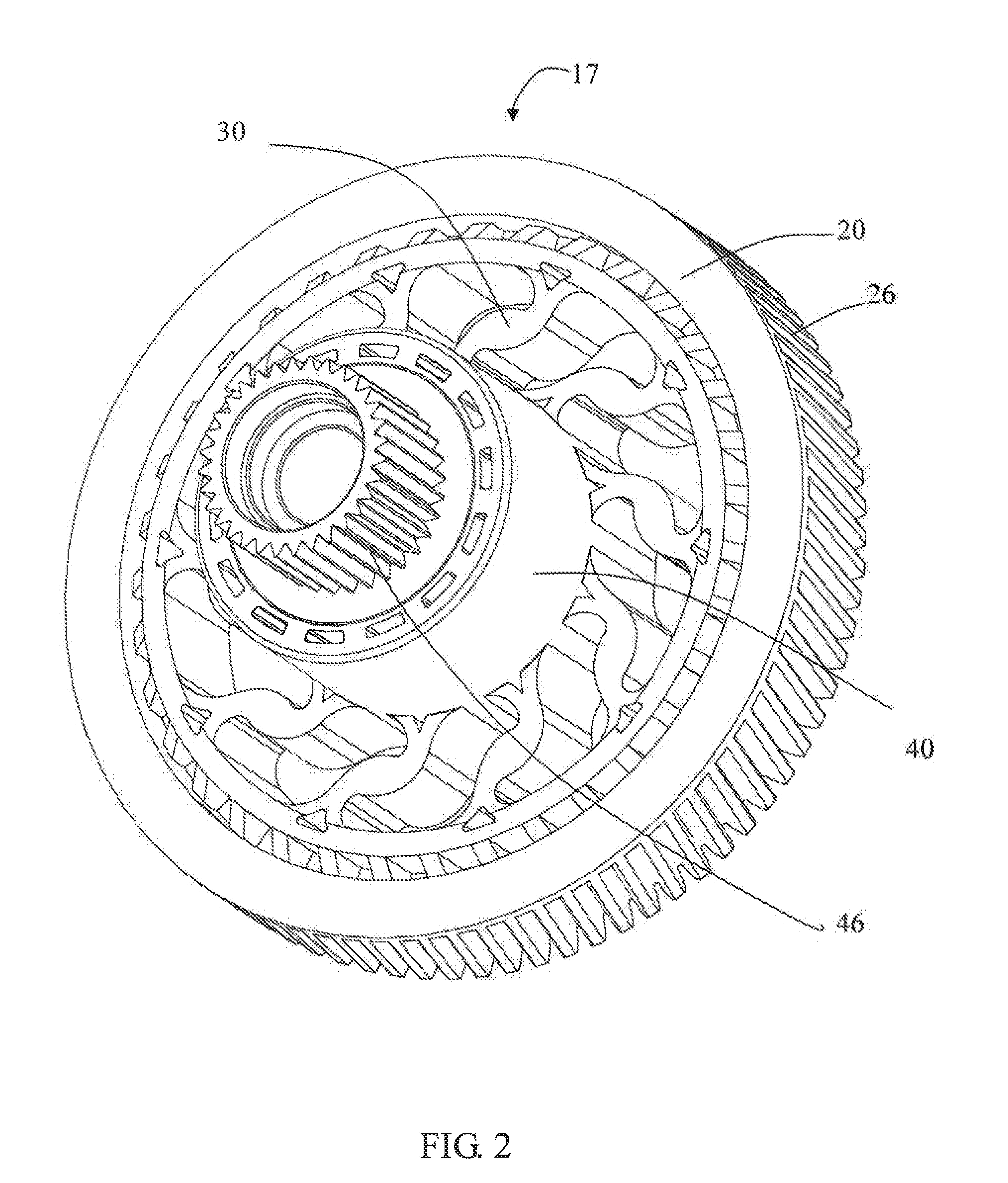
[0037]Referring to FIG. 2 and FIG. 3, the output gear 17 includes an outer ring portion 20 disposed in the housing, an inner ring portion 40 rotatably mounted on the stationary shaft and a plurality of spokes 30 connecting the inner ring portion 40 with the outer ring portion 20. An outer circumferential surface of the outer ring portion 20 is provided with teeth 26 which mate with the worm. An axial height of the inner ring portion 40 is greater than the axial height of...


PUM


Abstract

A gear includes an inner ring portion, an outer ring portion, and a number of spokes connecting the inner ring portion with the outer ring portion. An outer circumferential surface of the outer ring portion is provided with teeth. Each spoke includes a curve-shaped main portion, an inner end section at an inner end of the main portion which connects to the inner ring portion, and an outer end section at an outer end of the main portion which connects to the outer ring portion. At least one of the inner end section and outer end section is formed with a furcated structure.

Description

CROSS REFERENCE TO RELATED APPLICATIONS[0001]This non-provisional patent application claims priority under 35 U.S.C. §119(a) from Patent Application No. 201310359641.1 filed in The People's Republic of China on Aug. 16, 2014, the entire contents of which are hereby incorporated by reference.FIELD OF THE INVENTION[0002]This invention relates to a gearbox and in particular, to a gear of a gearbox suitable for a window lift motor assembly of a vehicle.BACKGROUND OF THE INVENTION[0003]Currently, manual vehicle window winders have been generally replaced by electric motor driven window lifts. The gear train is a key part of the electric window lift. Conventional window lift gear trains have output gears that can be generally classified into two categories: gears without rubber cushions and gears with rubber cushions. The gear without a rubber cushion is relatively simple in its overall design and has a small number of parts as well as low cost. However, the gear without a rubber cushion ...

Claims


Application Information

Patent Timeline
Patent Type & Authority Applications(United States)
IPC IPC(8): F16H55/17
CPCF16H55/17F16H55/14F16H2055/065F16H55/22Y10T74/1987
Inventor TA, JING NINGWANG, ZHI GUOLI, QIU MEIZHAO, YONG JUN
Owner JOHNSON ELECTRIC SA
Learn More