Charge control apparatus and charge control method
a control apparatus and charge control technology, applied in electrochemical generators, safety/protection circuits, transportation and packaging, etc., can solve the problems of increasing the cost and size of the apparatus, and increasing the required charging time proportionally. , to achieve the effect of preventing the increase of the required charging time, increasing the size of the apparatus, and increasing the cost of the apparatus
- Summary
- Abstract
- Description
- Claims
- Application Information
AI Technical Summary
Benefits of technology
Problems solved by technology
Method used
Image
Examples
first exemplary embodiment
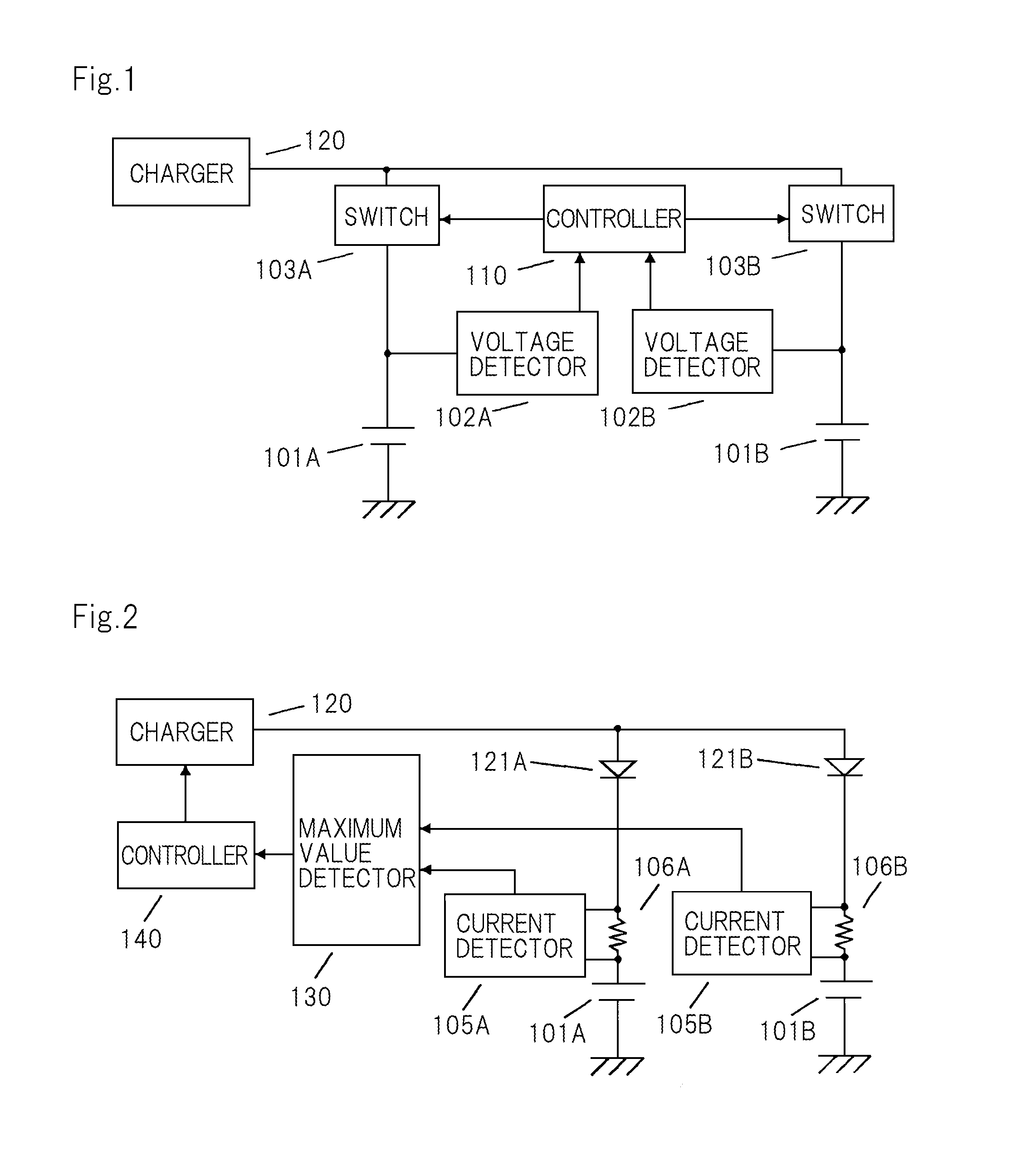
[0045]FIG. 2 is a block diagram showing a configuration of a charge control apparatus of a first exemplary embodiment of the present invention.
[0046]Referring to FIG. 2, the charge control apparatus charges two batteries 101A and 101B, and includes current detectors 105A and 105B, current detection resistor elements 106A and 106B, reverse-current protectors 121A and 121B, charger 120, maximum value detector 130, and controller 140.
[0047]Batteries 101A and 101B are connected in parallel to charger 120 having a variable output voltage.
[0048]An output line of charger 120 is connected to one end of reverse-current protector 121A, and connected to one end of reverse-current protector 121B.
[0049]The other end of reverse-current protector 121A is connected to battery 101A via current detection resistor element 106A. The other end of reverse-current protector 121B is connected to battery 101B via current detection resistor element 106B.
[0050]Reverse-current protectors 121A and 121B function...
second exemplary embodiment
[0080]FIG. 5 is a block diagram showing a configuration of a charge control apparatus of a second exemplary embodiment of the present invention.
[0081]The charge control apparatus of this exemplary embodiment includes not only the configurational elements shown in FIG. 2 but also current setters 142A and 142B and error amplifiers 141A and 141B. This apparatus is different in this point from the apparatus of the first exemplary embodiment. In FIG. 5, the same signs are assigned to the same elements as those of the first exemplary embodiment. The description is omitted.
[0082]Current setter 142A outputs an upper limit value of the charging current for battery 101A. Current setter 142B outputs an upper limit value of the charging current for battery 101B. If the upper limit values of charging currents for respective batteries 101A and 101B are the same, the output values of current setters 142A and 142B are the same. If the upper limit value of charging current for battery 101A is differ...
example 1
[0100]An example of the charge control apparatus of first exemplary embodiment is described as a first example of the present invention.
[0101]The charge control apparatus of this example has the configuration shown in FIG. 2. The configurational elements are configured as follows.
[0102]The maximum voltage value that charger 120 can supply is 4.2 V. The current supply capacity of charger 120 is 10 A at the maximum.
[0103]Each of reverse-current protectors 121A and 121B is made of an ideal diode circuit that is constructed using an FET.
[0104]Each of batteries 101A and 101B is made of a lithium-ion battery having a capacity of 10 Ah and an allowable charging current of 5 A, and its internal resistance is 10 mΩ. The open-circuit voltage of battery 101A is 3.50 V, and the open-circuit voltage of battery 101B is 3.55 V.
[0105]The resistance values of current detection resistor elements 106A and 106B are each 10 mΩ. Current detectors 105A and 105B multiply the respective voltages across the ...
PUM
 Abstract
Description
Claims
Application Information
 - R&D
- Intellectual Property
- Life Sciences
- Materials
- Tech Scout
- Unparalleled Data Quality
- Higher Quality Content
- 60% Fewer Hallucinations
Browse by: Latest US Patents, China's latest patents, Technical Efficacy Thesaurus, Application Domain, Technology Topic, Popular Technical Reports.
© 2025 PatSnap. All rights reserved.Legal|Privacy policy|Modern Slavery Act Transparency Statement|Sitemap|About US| Contact US: help@patsnap.com


