Double pole-double throw proximity switch

a proximity switch and double pole technology, applied in the field of electric switches, can solve problems such as nuclear meltdown, runaway nuclear reaction, loss of cooling fluid,

Active Publication Date: 2015-02-19
GENERAL EQUIP & MFG COMPANY INC D B A TOPWORX
View PDF0 Cites 15 Cited by
  • Summary
  • Abstract
  • Description
  • Claims
  • Application Information

AI Technical Summary

Benefits of technology

[0008]A proximity switch includes a body tube having a blind bore, a closed end, and an open end; a magnetic proximity switch assembly disposed inside the blind bore; a hermetic seal covering the blind bore between the magnetic proximity switch assembly and the open end; a crush ring disposed against an annular shoulder defined in a surface of the blind bore between the hermetic seal and the open end; a crush ring compression device having a threaded plug body that screws into the open end of the blind bore and sealingly engages the crush ring; and a potting filling space between the crush ring compression device and the hermetic seal. The hermetic seal, the potting, and the crush ring compression device seal the blind bore and protect the magnetic proximity switch during pressurization and submergence testing or during exposure to harsh environmental factors.

Problems solved by technology

In extreme emergencies, such as containment vessel breaches, nuclear reactors can experience a loss of cooling fluid, which could potentially lead to a runaway nuclear reaction (i.e., nuclear meltdown).
However, these high amp rated mechanical switches suffer from various drawbacks, such as low performance at low current (due to resistance problems), requiring a lever arm that connects to the target, complicated internal moving parts (e.g., springs, cams, and the like), multiple points of potential contamination ingression, supplementary repair and regular maintenance of the internal moving components, and a short service life, generally less than about 9 years.

Method used


Image

  • Double pole-double throw proximity switch
  • Double pole-double throw proximity switch
  • Double pole-double throw proximity switch

Examples


Embodiment Construction

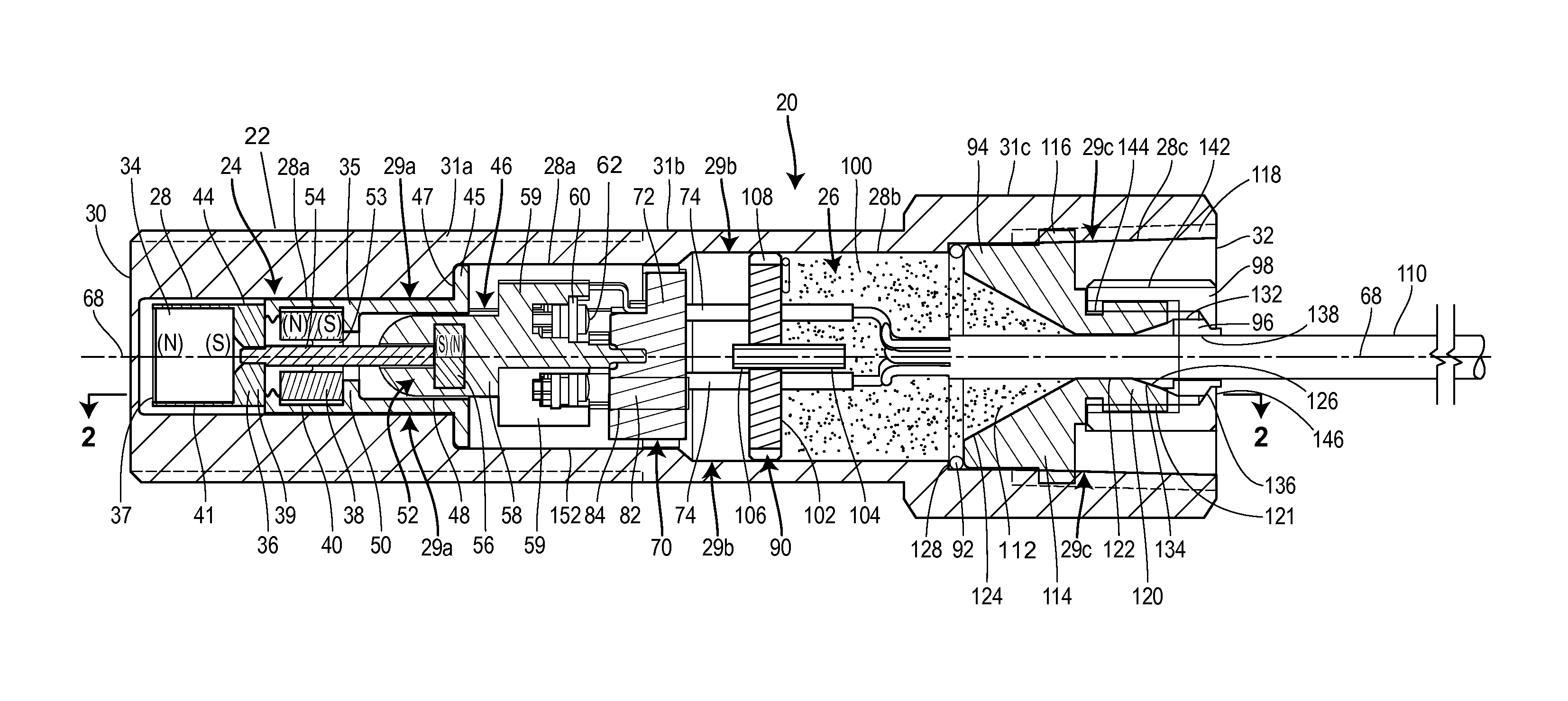
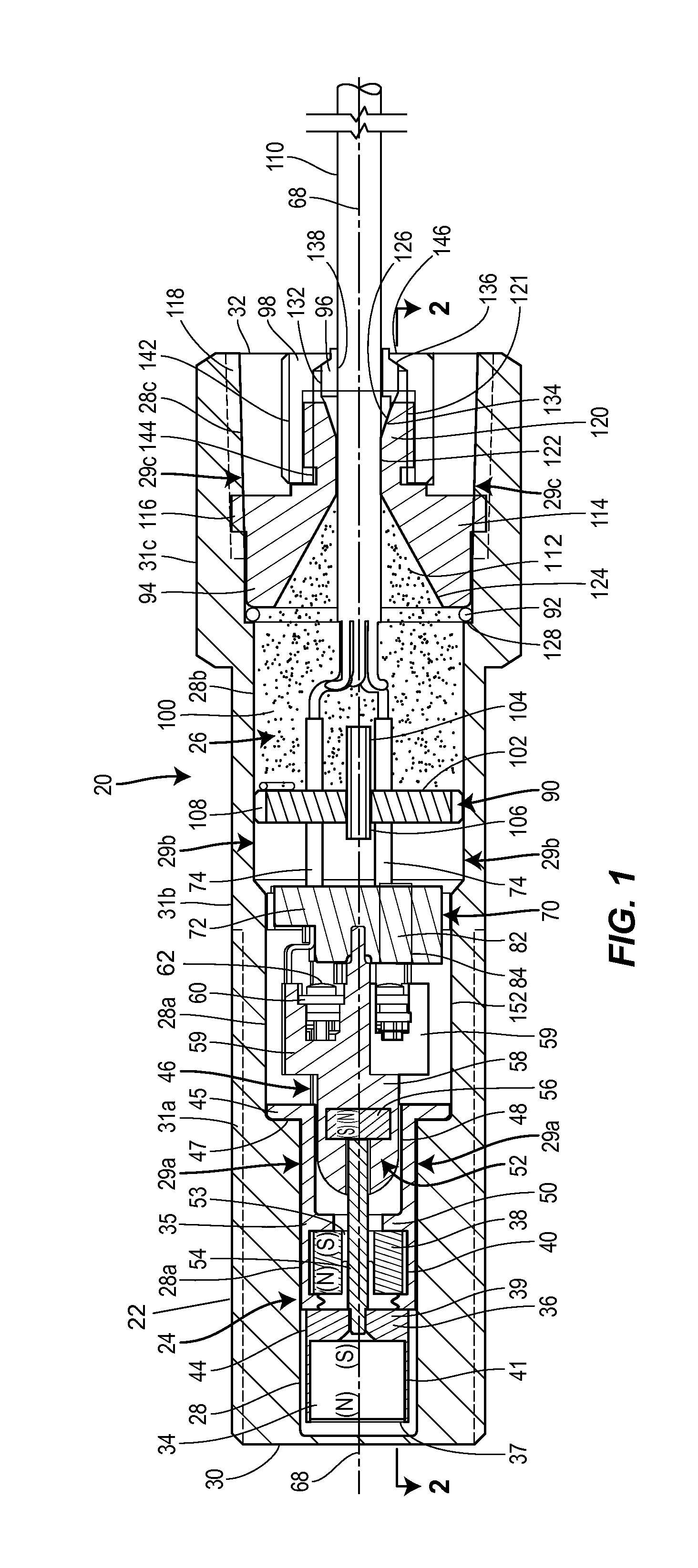
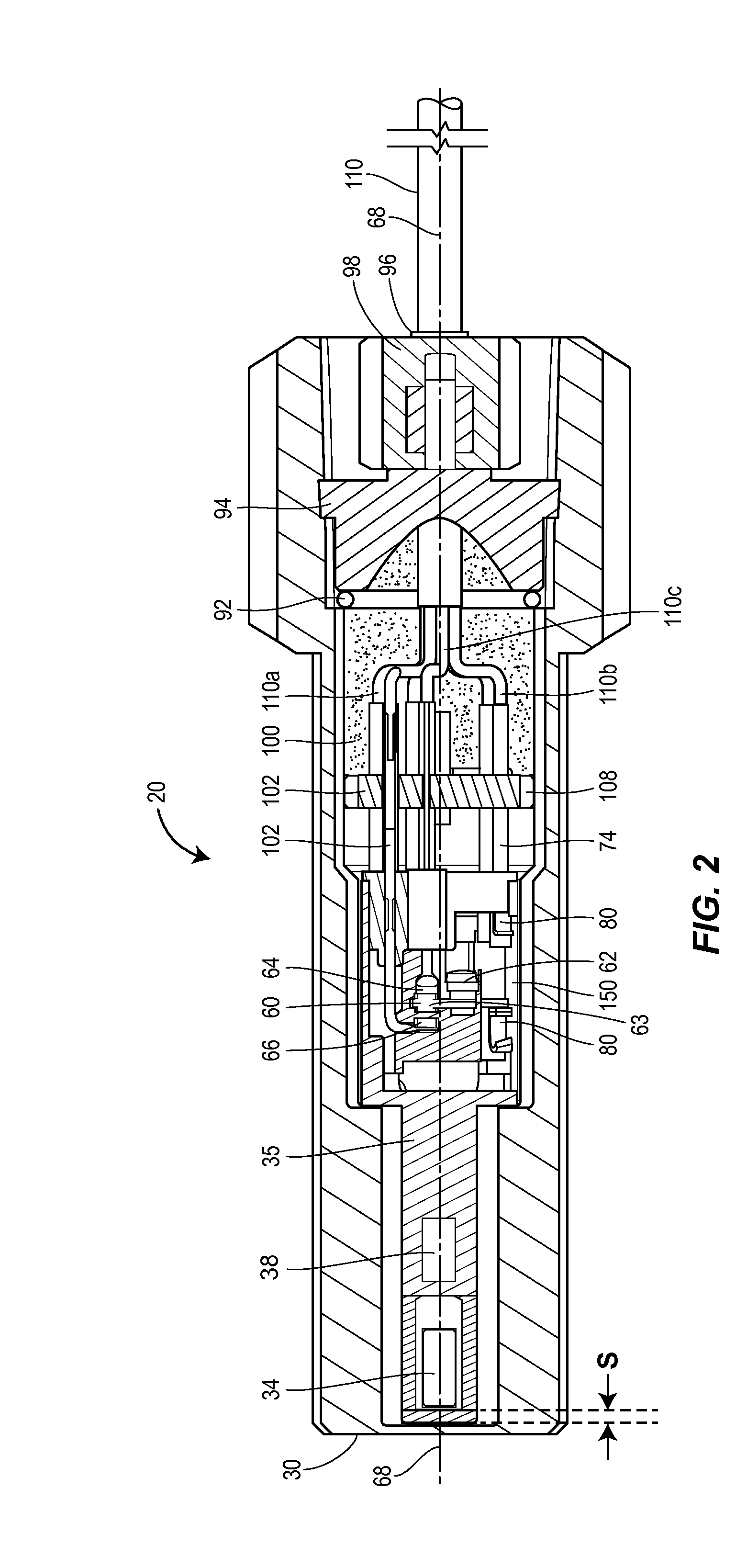
[0023]Each proximity switch preferably includes a switch assembly having an array of magnets disposed near a face of the switch to create an internal magnetic bias to maintain the switch in a normal first position that completes a first circuit. The first circuit can be either a normally open or a normally closed circuit depending on how the switch assembly is wired. When the internal magnetic bias is interrupted or overpowered, such as by a target made of ferrous metal or preferably magnetized material moved to within a certain distance of the face of the switch, the change in bias causes a set of electrical contacts to shift to a second position that completes a second circuit as long as the target is within the certain distance. When the target is removed from the face of the switch, the array of magnets causes the switch to shift back to the first position and thereby switch back to the first circuit again. As a result, each proximity switch snaps positively between the first an...


PUM


Abstract

Proximity switches include a hermetically sealed unit that can be used in harsh environments and under significant pressures, such as underwater and in nuclear power facilities, without having any parts that would require replacement or periodic maintenance. The proximity switches are preferably switches actuated by physical movement of a contact in response to changing magnetic forces. The switches are preferably disposed in a body tube optionally including a hermetic seal assembly to seal an open end of the body tube and / or a ferrule that prevents electrical wires attached to the switch inside the body tube from being pulled away from the switch. Further, the switches preferably maintain a contact pressure between electrical contacts sufficient to withstand acceleration seismic testing of 10 g with no contact discontinuity.

Description

RELATED APPLICATIONS[0001]This application is a divisional of U.S. patent application Ser. No. 13 / 728,050, filed Dec. 27, 2012, the entirety of which is hereby incorporated by reference herein.BACKGROUND[0002]1. Field of the Disclosure[0003]The invention generally relates to electrical switches and more specifically to double pole—double throw proximity switches for use in nuclear environments.[0004]2. Related Technology[0005]Nuclear reactors require robust control systems to ensure that the nuclear reaction can be shut down in any emergency. In extreme emergencies, such as containment vessel breaches, nuclear reactors can experience a loss of cooling fluid, which could potentially lead to a runaway nuclear reaction (i.e., nuclear meltdown). In such situations, the control systems of the nuclear reactor must be capable of shutting down the nuclear reactor regardless of damage or other non-normal operating conditions. To ensure that the control systems are capable of shutting down th...

Claims


Application Information

Patent Timeline
Patent Type & Authority Applications(United States)
IPC IPC(8): H01H36/00
CPCH01H36/0073H01H9/04H01H36/00H01H2231/044
Inventor LAFOUNTAIN, ROBERT LYNNMERRIFIELD, GREGORY CURTIS
Owner GENERAL EQUIP & MFG COMPANY INC D B A TOPWORX
Why Eureka
Try Eureka