Millimeter wave test fixture for an integrated circuit device under test

a technology of integrated circuit devices and test fixtures, which is applied in the direction of measurement devices, instruments, antenna radiation diagrams, etc., can solve the problems that the conventional radio frequency test system using cables for electrical conduction cannot be used for mmw testing of an ic dut, inconvenience during use, and the inability to achieve accurate attenuation of mmw signal by the attenuator used in the conventional mmw test equipmen

Inactive Publication Date: 2015-02-19
URTN
View PDF10 Cites 17 Cited by
  • Summary
  • Abstract
  • Description
  • Claims
  • Application Information

AI Technical Summary

Benefits of technology

[0012]The MMW source is secured in the second RF anechoic chamber in the metallic casing for generating and radiating a predetermined MMW signal that has desired MMW characteristics.
[0013]The second antenna is secured in the second RF anechoic chamber in the metallic casing. The second antenna is opposite to and aligned with the MMW source for re

Problems solved by technology

A conventional radio frequency test system using cables for electrical conduction cannot be used for MMW testing of an IC DUT, which includes, for example, an array of antennas built therein.
In addition, prior to testing, the IC DUT disposed in the RF anecho

Method used


Image

  • Millimeter wave test fixture for an integrated circuit device under test
  • Millimeter wave test fixture for an integrated circuit device under test
  • Millimeter wave test fixture for an integrated circuit device under test

Examples


Embodiment Construction

[0022]Before the present invention is described in greater detail, it should be noted that like elements, are denoted by the same reference numerals throughout the disclosure.

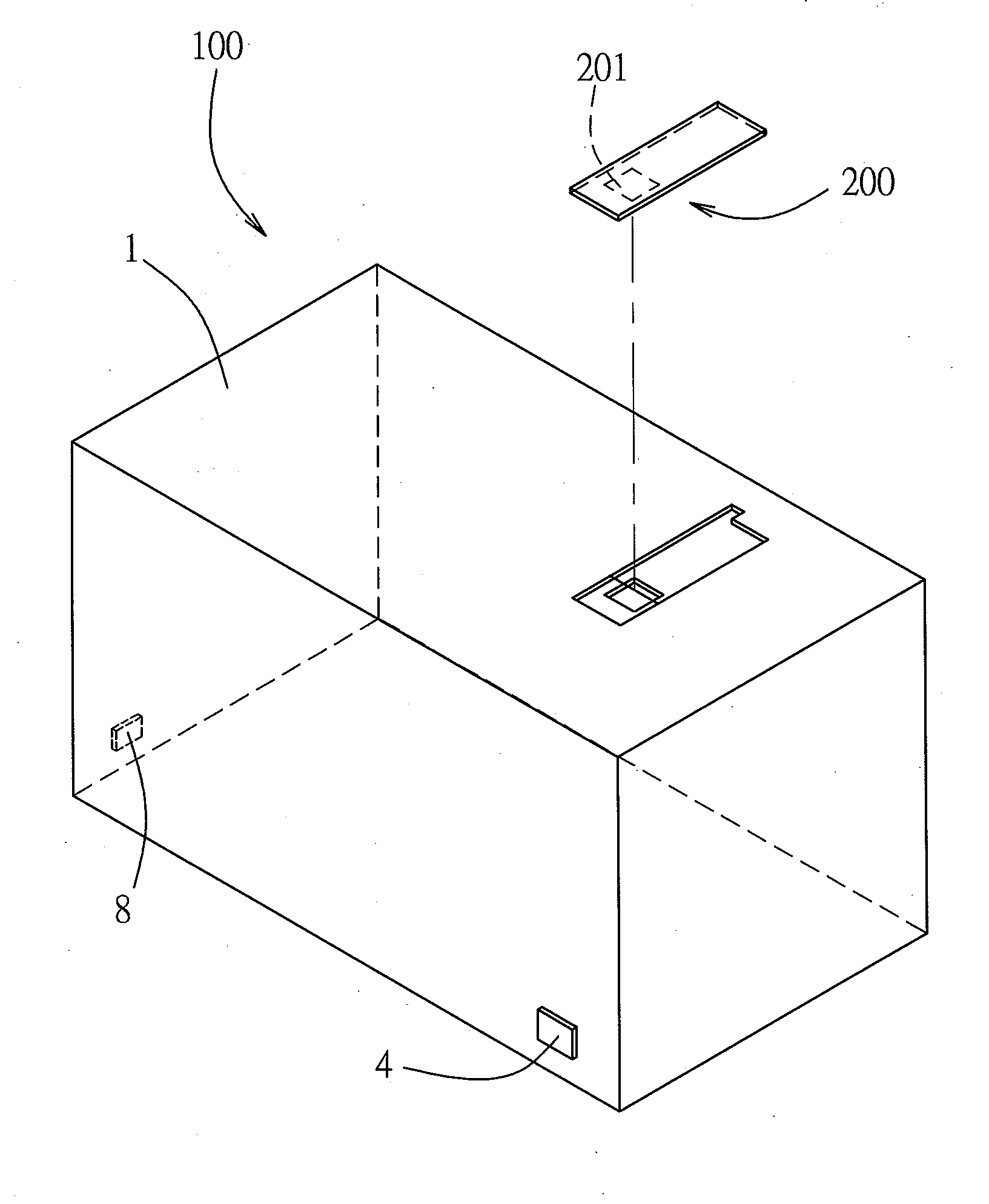
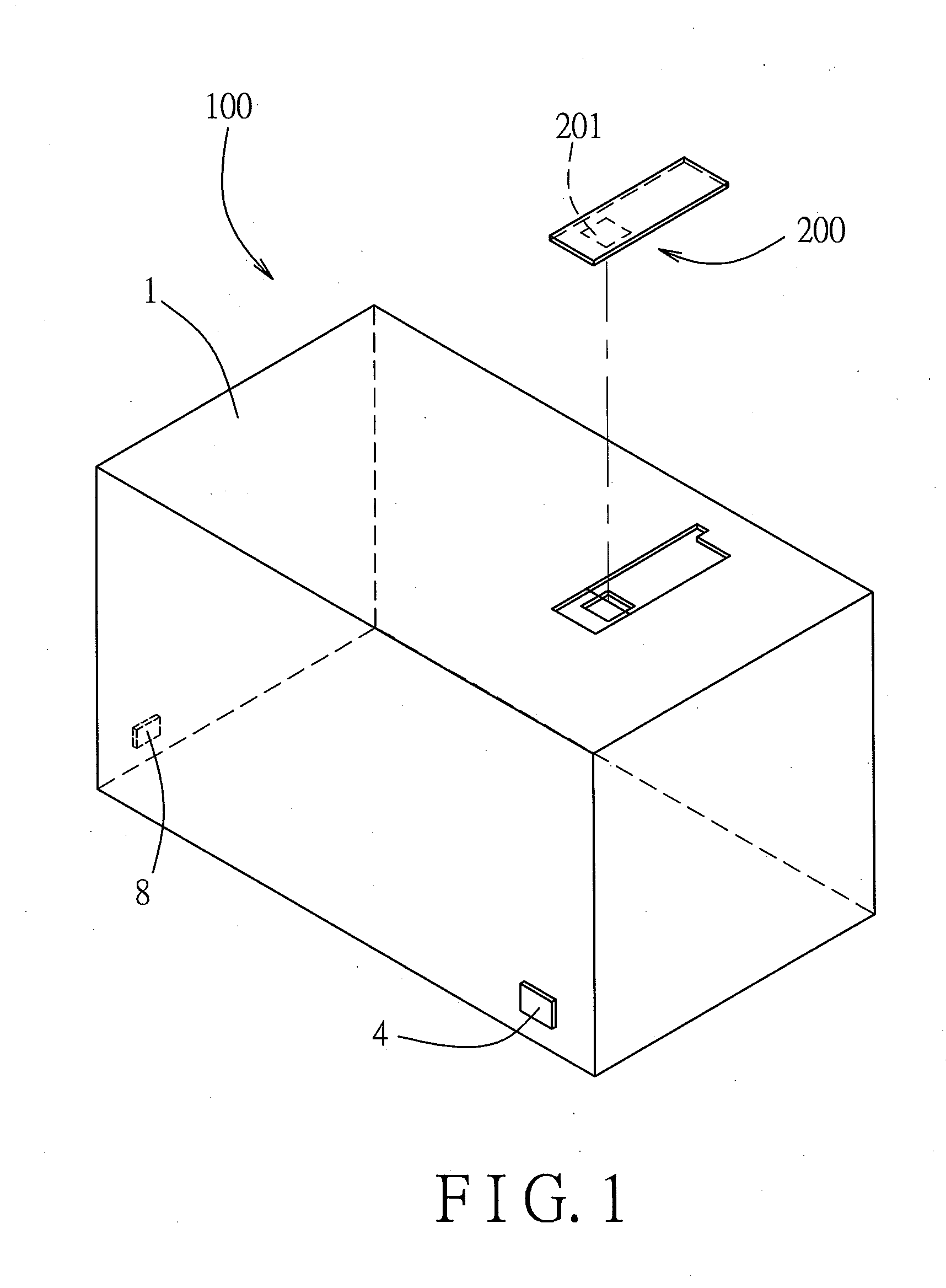
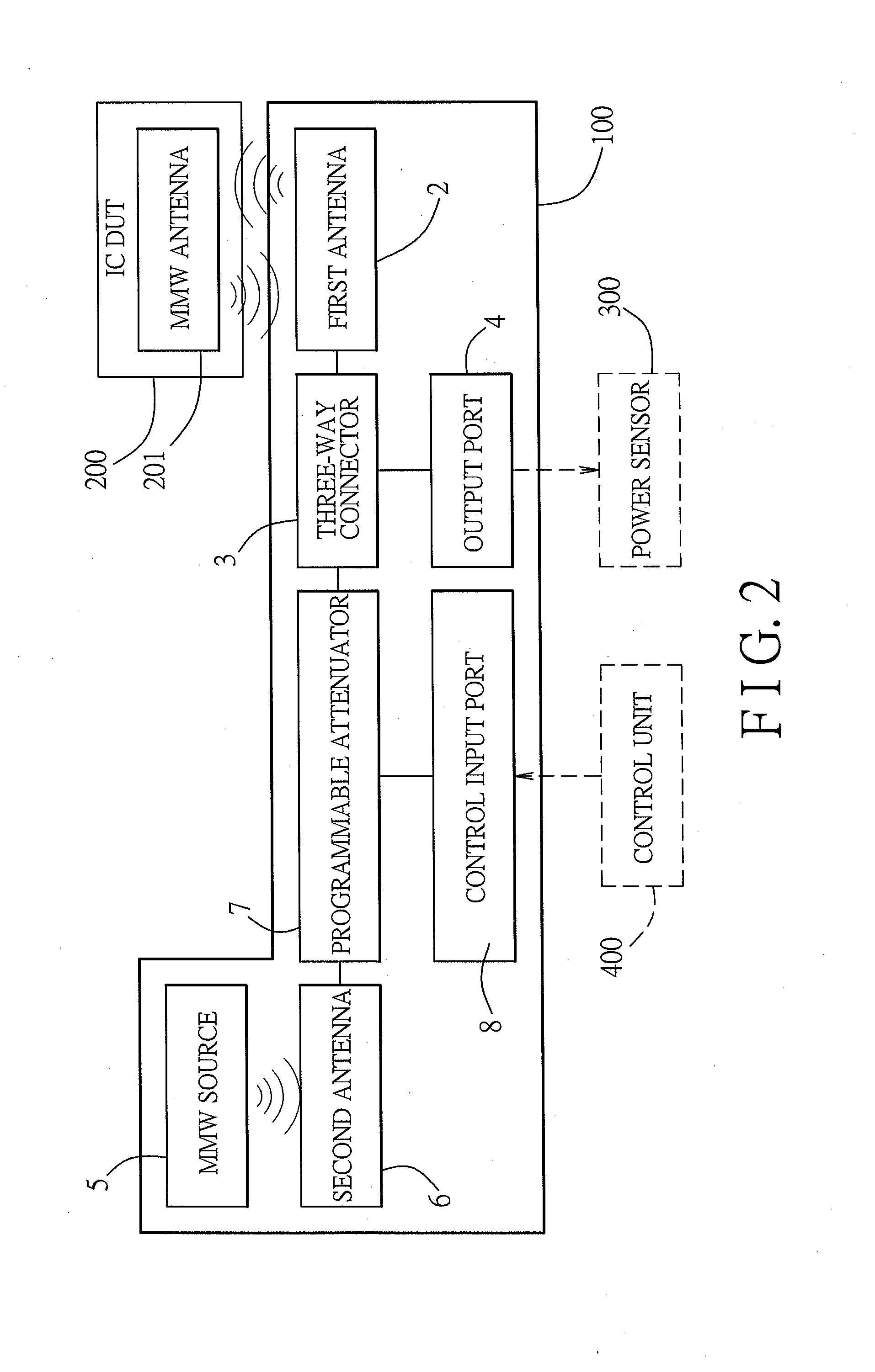
[0023]Referring to FIGS. 1 to 3, the first preferred embodiment of a test fixture 100 for an integrated circuit (IC) device under test (DUT) 200 according to the present invention is used to test transmission and reception characteristics of the IC DUT 200. In this embodiment, the IC DUT 200, such as a signal transceiving module, has an integrated millimeter wave (MMW) antenna 201. The test fixture 100 includes a metallic casing 1, a first antenna 2, a three-way connector 3, an output port 4, an MMW source 5, a second antenna 6, a programmable attenuator 7 and a control input port 8.

[0024]The metallic casing 1 is configured with rectangular first and second radio frequency (RF) anechoic chambers 11, 12, which are arranged in a horizontal direction in this embodiment. Each of the first and second RF anechoic cha...


PUM


Abstract

A test fixture for an integrated circuit (IC) device under test (DUT) includes: a metallic casing; and first and second antennas secured respectively in first and second RF anechoic chambers in the metallic casing and coupled to a programmable attenuator. The IC DUT is positioned on or in the metallic casing so that an integrated millimeter wave (MMW) antenna thereof is aligned with the first antenna to radiate an MMW signal toward the first antenna through the first RF anechoic chamber. A predetermined MMW signal, which is radiated from an MMW source secured in the second RF anechoic chamber toward the second antenna, is received by the second antenna, is attenuated by the attenuator, and is radiated by the first antenna toward the MMW antenna of the IC DUT.

Description

CROSS-REFERENCE TO RELATED APPLICATION[0001]This application claims priority of Taiwanese Application No. 102129304, filed on Aug. 15, 2013.BACKGROUND OF THE INVENTION[0002]1. Field of the Invention[0003]The invention relates to a test fixture, and more particularly to a millimeter wave (MMW) test fixture for an integrated circuit (IC) device under test (DUT).[0004]2. Description of the Related Art[0005]A conventional radio frequency test system using cables for electrical conduction cannot be used for MMW testing of an IC DUT, which includes, for example, an array of antennas built therein. Therefore, there is proposed an MMW test equipment for such IC DUT. The conventional MMW test equipment adopts the most common test setup, and includes: a radio frequency (RF) anechoic test room; a test antenna disposed in the RF anechoic test room for radiating an MMW signal from a signal source, e.g., a 60 GHz signal; and an electromagnetic wave absorption material, such as one or more stacks ...

Claims


Application Information

Patent Timeline
IPC IPC(8): G01R29/10
CPCG01R29/105G01R1/045G01R31/2822
Inventor CHIN, YUEH-JUNG
Owner URTN
Why Eureka
Try Eureka