Orthodontic Bracket

a bracket and orthodontic technology, applied in the field of orthodontic brackets, can solve the problems of inability to control the resulting treatment force applied in all planes of space, long treatment time for patients, and advanced clinical practice skills, and achieve the effect of reducing the number of patients

Active Publication Date: 2015-02-19
PREMIER ORTHODONTIC DESIGNS LLLP
View PDF20 Cites 34 Cited by
  • Summary
  • Abstract
  • Description
  • Claims
  • Application Information

AI Technical Summary

Benefits of technology

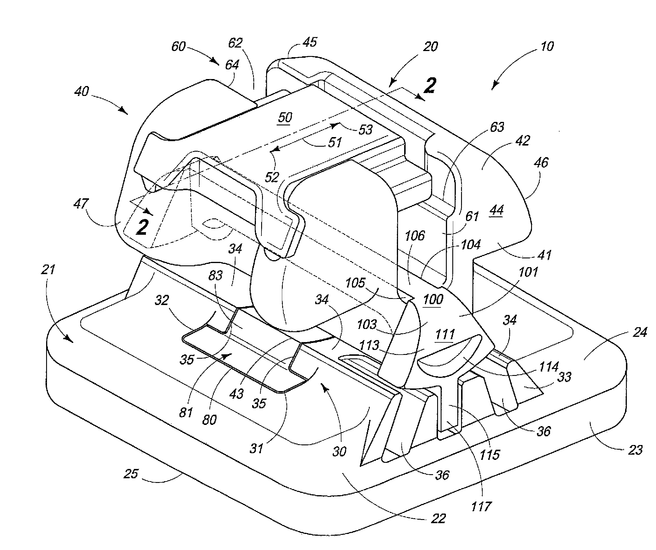
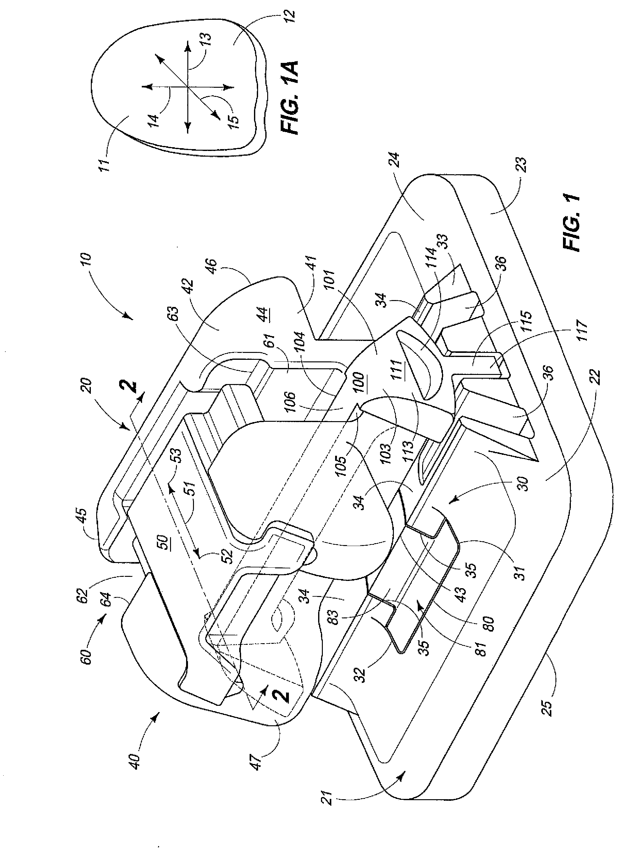
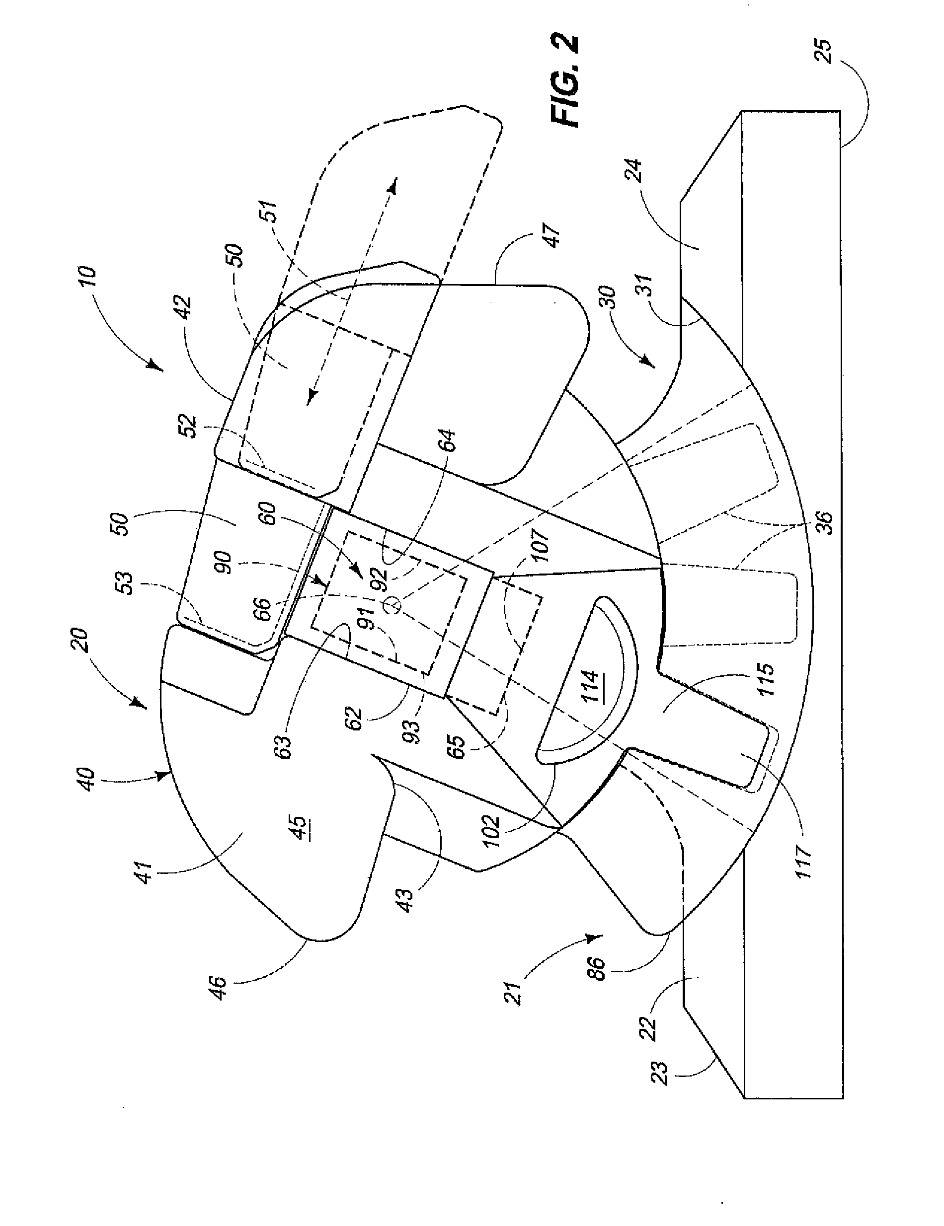
[0010]Moreover, another aspect of the present invention relates to an orthodontic bracket which includes a bracket base having a pad which is releasably affixed to an anterior facing surface of a patient's tooth, and wherein the bracket base has an anterior facing surface which defines a coupling portion having a curved anterior facing surface, and wherein a multiplicity of engagement regions are formed in a predetermined spatial pattern in the curved anterior facing surface of the coupling portion; a bracket body which matingly, and moveably cooperates with the bracket base, and which has an anterior facing surface defining an aperture, and which further defines, in part, an arch wire slot having spaced, top and bottom surfaces, and a given cross-sectional dimension, and wherein the transversely disposed arch wire slot communicates with the aperture which is defined by the anterior facing surface of the bracket body, and is further accessible from the anterior facing surface of the bracket body, and wherein the bracket body has a complementary, curved, posterior facing surface which matingly, and moveably engages the curved, anterior facing surface of the coupling portion of the bracket base; a bracket body insert which is releasably received within the transversely disposed arch wire slot, and which ...

Problems solved by technology

This activity not only took long periods of time, and advanced clinical practice skills, but it was nearly impossible for most clinicians to control the resulting treatment forces applied in all planes of space.
As a result, treatment times for patients were often unduly long in duration, and the resulting treatment forces which were applied often had a negative long term impact on the patient's bone and tissue.
However, this design still lacked adequate third order control of tooth axial inclination.
The term “straight wire orthodontics” misled many clinicians to believe that only one bracket torque prescription on each anterior tooth was adequate to express a final desired tooth position.
Unfortunately, without bending rectangular arch wires to individualize finishing torque on individual teeth, this had nearly the same effect as treating patients using only round wires in the bracket arch wire slot.
Over the years, some clinicians have tried to fill the arch wire slot with larger cross-sectional rectangular arch wires to achieve third order control, but many have found it difficult to finally position teeth due to the binding, and f...

Method used


Image

  • Orthodontic Bracket
  • Orthodontic Bracket
  • Orthodontic Bracket

Examples


Embodiment Construction

[0041]This disclosure of the invention is submitted in furtherance of the constitutional purposes of the U.S. Patent Laws “to promote the progress of science and useful arts” (Article 1, Section 8).

[0042]The present invention, in its various forms, is generally indicated by the numeral 10 in FIG. 1 and following. For purposes of the present application, and for the several forms of the invention as described, hereinafter, it will be understood that the various forms of the invention are employed to be releasably affixed to a patient's tooth 11 as seen in FIG. 1A, and in particular, to the anterior facing surface 12 thereof. The orthodontic bracket 10, in its various forms, and in combination with the arch wire as will be described, hereinafter, is employed to provide a multiplicity of selective torque expressions which individually forcibly act upon the patient's tooth 11. For purposes of this patent application, the term “torque expression” as used hereinafter, is defined as the fo...


PUM


Abstract

An orthodontic bracket is described, and which includes a bracket base, which is releasably affixed to a patient's tooth; a bracket body borne on the bracket base, and which defines an arch wire slot, and wherein the arch wire slot has a selectively adjustable cross-sectional dimension; and an arch wire received within the arch wire slot and wherein the bracket body acting in combination with the arch wire is adjustable so as to provide a multiplicity of selective torque expressions, which act upon a patient's tooth.

Description

TECHNICAL FIELD[0001]The present invention relates to an orthodontic bracket, and more specifically to an orthodontic bracket which defines a transversely disposed arch wire slot which is selectively adjustable so as to provide a variable cross-sectional dimension, and which further provides a multiplicity of selective torque expressions which individually forcibly act upon a patient's tooth.BACKGROUND OF THE INVENTION[0002]In our earlier U.S. patent application Ser. No. 13 / 745,638, and which was filed on Jan. 18, 2013, we described an orthodontic bracket which when used in combination with an arch wire provides first, second, and third orders of movement of the patient's tooth without a clinically predetermined manipulation of the arch wire which is received in the transversely disposed arch wire slot. The various forms of the invention as disclosed in this pending US patent application provides a multitude of patient and clinical advantages not possible in orthodontic appliances w...

Claims


Application Information

Patent Timeline
IPC IPC(8): A61C7/28
CPCA61C7/28A61C7/287A61C7/30A61C7/14A61C7/141
Inventor DAMON, PAUL L.DAMON, DWIGHT H.
Owner PREMIER ORTHODONTIC DESIGNS LLLP
Why Eureka
Try Eureka