Dental syringe tip devices, systems and methods

a technology applied in the field of dental systems, methods and devices for dental syringes, can solve the problems of contaminated syringe tips, leakage of water into designated pressurized air ports of dental syringes and tips, and inability to meet the needs of patients, so as to reduce the likelihood of fluid leakage, reduce the possibility of leakage, or eliminate the

Active Publication Date: 2015-02-19
BERKELY DONOVAN WINSTON
View PDF12 Cites 19 Cited by
  • Summary
  • Abstract
  • Description
  • Claims
  • Application Information

AI Technical Summary

Benefits of technology

[0007]Another aspect of the dental systems, methods and devices described herein is the recognition of a need to reduce the likelihood of fluid leakage from one passage to a second passage. For example, some dental syringes and tips can leak water into the designated pressurized air port. This can result in some amount of water being ejected from the pressurized air port when the operator intended that only pressurized air be released. As should be apparent, this can pose potentially significant issues when leaked fluid is ejected from an improper port. As such, one feature of the dental systems, methods and devices described herein is a reduction, or potential elimination, of leakage from one fluid channel to another fluid channel.

Problems solved by technology

Due to the proximity of the syringe tip with the target location, it is inevitable that at least some contaminants from the patient, such as bacteria, viruses, and bodily fluids, will contact and contaminate the syringe tip.
Dental syringes are often limited to a fixed level of fluid pressure such as a fixed water output pressure from the water port and fixed air pressure output from the pressurized air port.
For example, some dental syringes and tips can leak water into the designated pressurized air port.
This can result in some amount of water being ejected from the pressurized air port when the operator intended that only pressurized air be released.
As should be apparent, this can pose potentially significant issues when leaked fluid is ejected from an improper port.

Method used


Image

  • Dental syringe tip devices, systems and methods
  • Dental syringe tip devices, systems and methods
  • Dental syringe tip devices, systems and methods

Examples


Embodiment Construction

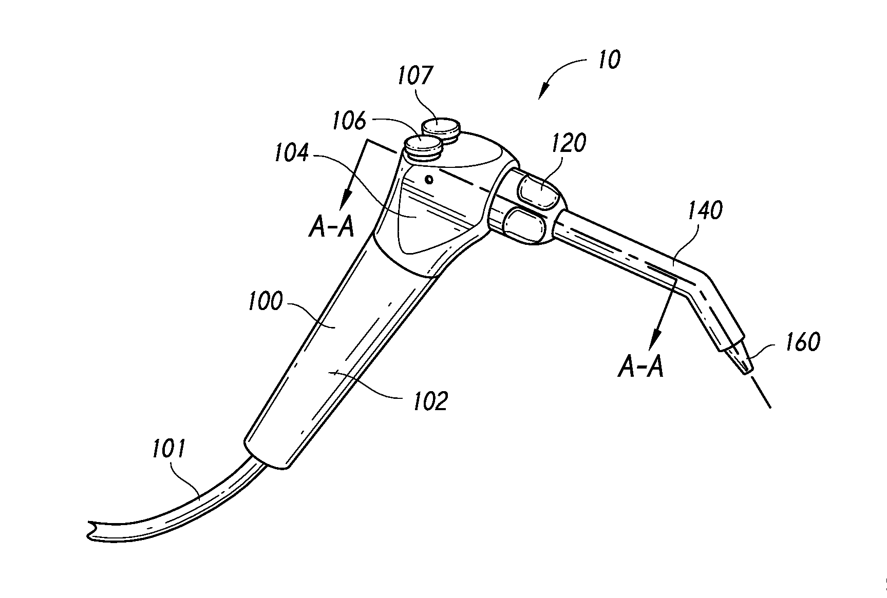
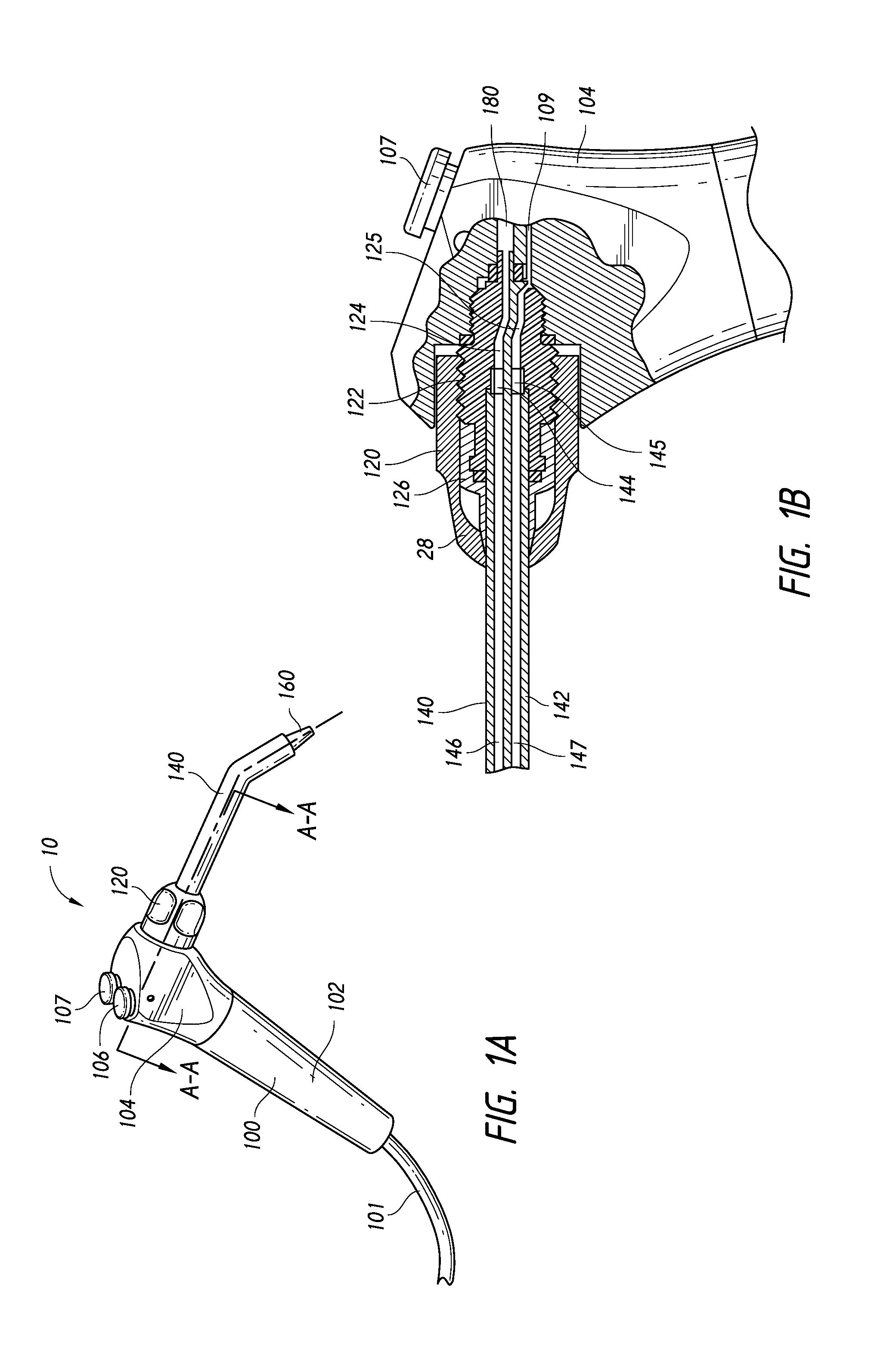
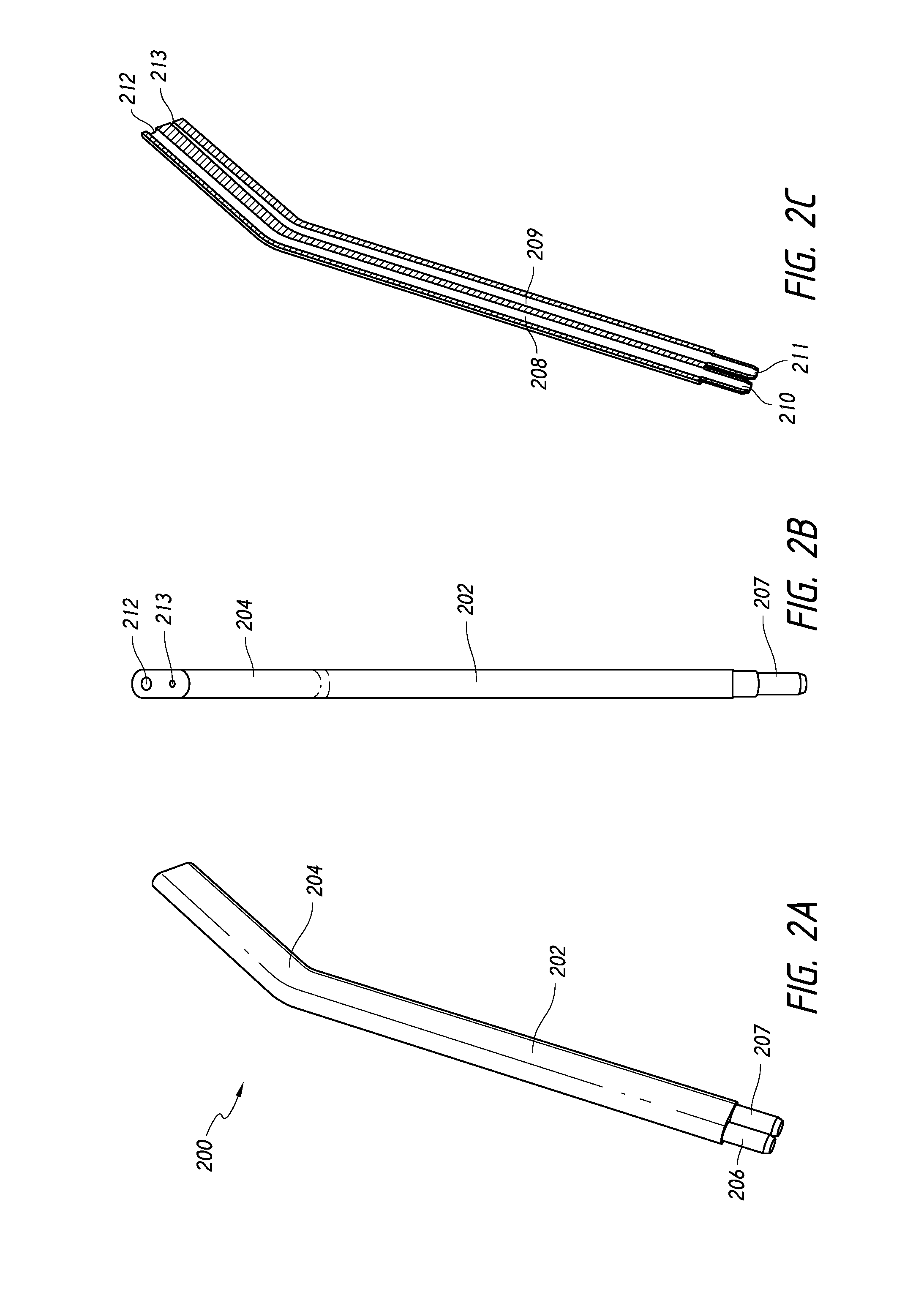
[0229]As will be described, the present application relates to a syringe tip devices and system and methods for producing and using such a syringe tip device and system. It should be appreciated that while the figures and description herein often refers to syringe tips, which can be used on a dental syringe, in modified embodiments the syringe tips can be applied to other types of fluid flow devices in which a syringe tip can be used to direct the fluid flow from the fluid flow device. It should be appreciated that, for purposes of this disclosure, “fluid” includes gases, liquids, and solids capable of being transported via gas or liquid transport, such as solid powders and the like. For example, the term “fluid” can include abrasives, adhesives and other types of bonding chemicals, sealants, therapeutic agents such as anesthetics, medicines and antibiotics, CaOH pastes or powders, prophy paste, whitening gels, mouthwash, periodontal rinse solutions, and any other gas, liquid, solid...


PUM


Abstract

A dental syringe tip system for attachment to a dental syringe. The dental syringe tip system can include components such as an outer core, an inner core, and a carrier which can be combined in a multitude of combinations to achieve different fluid flow characteristics, such as discharge pressure and discharge pattern, through the dental syringe tip. The outer core and inner core can have passages designed to modify fluid flow characteristics. In addition, the outer core and inner core can have additional connectors for receiving fluids from sources other than a dental syringe. Some or all of the components can be separate to be assembled by a manufacturer or an end-user. Assembly of multiple components can be facilitated by retention features located on the components.

Description

RELATED APPLICATIONS[0001]The present application claims priority to U.S. Provisional Application No. 61 / 914,285, filed Dec. 10, 2013, U.S. Provisional Application No. 61 / 895,901, filed Oct. 25, 2013, and U.S. Provisional Application No. 61 / 866,444, filed Aug. 15, 2013, the entire contents of each of which is hereby expressly incorporated by reference and is to be considered a part of this specification.BACKGROUND[0002]1. Field[0003]The present inventions relates to dental systems, methods and devices for dental syringes.[0004]2. Description of the Related Art[0005]The dental syringe is a multi-purpose dental apparatus which is often used by dentists, dental assistants, dental hygienists, and other such personnel for a wide-range of dental visits. The dental syringe often includes both a water port and a pressurized air port and can be used for providing irrigation to a target site, clearing or removing debris from a target site, drying a target site for bonding with another dental ...

Claims


Application Information

Patent Timeline
Patent Type & Authority Applications(United States)
IPC IPC(8): A61C17/02A61C17/022A61C1/08
CPCA61C17/0202A61C17/022A61C1/088A61C17/02A61C17/0217
Inventor BERKELY, DONOVAN WINSTONWASYLUCHA, BRYAN M.
Owner BERKELY DONOVAN WINSTON
Why Eureka
Try Eureka