
Systems, articles and methods for signal routing in wearable electronic devices

a technology of electronic devices and signal routing, applied in the field of wearable electronic devices, can solve the problems of inconvenient hand(s) encumbered by the device itself, affecting affordability, and more sophisticated functionality,

Active Publication Date: 2015-02-19
META PLATFORMS TECH LLC
View PDF39 Cites 72 Cited by
  • Summary
  • Abstract
  • Description
  • Claims
  • Application Information

AI Technical Summary

Benefits of technology

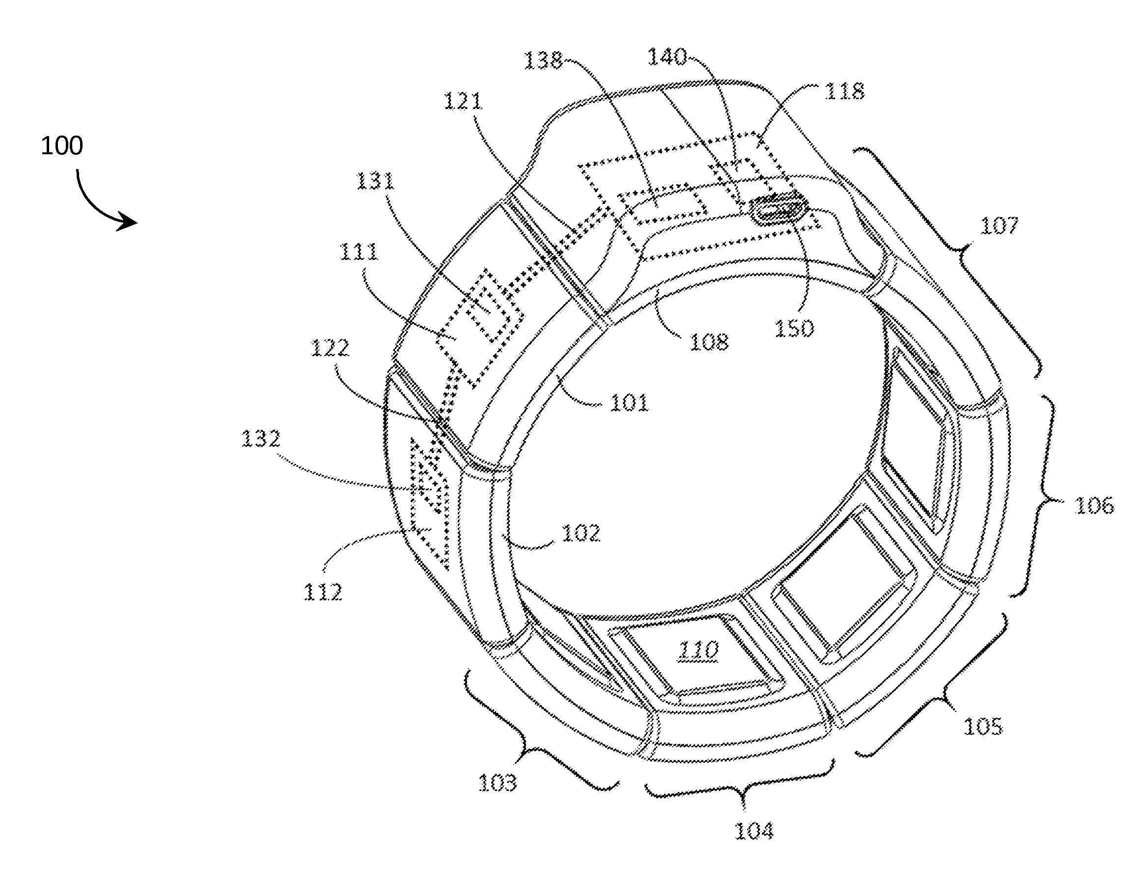
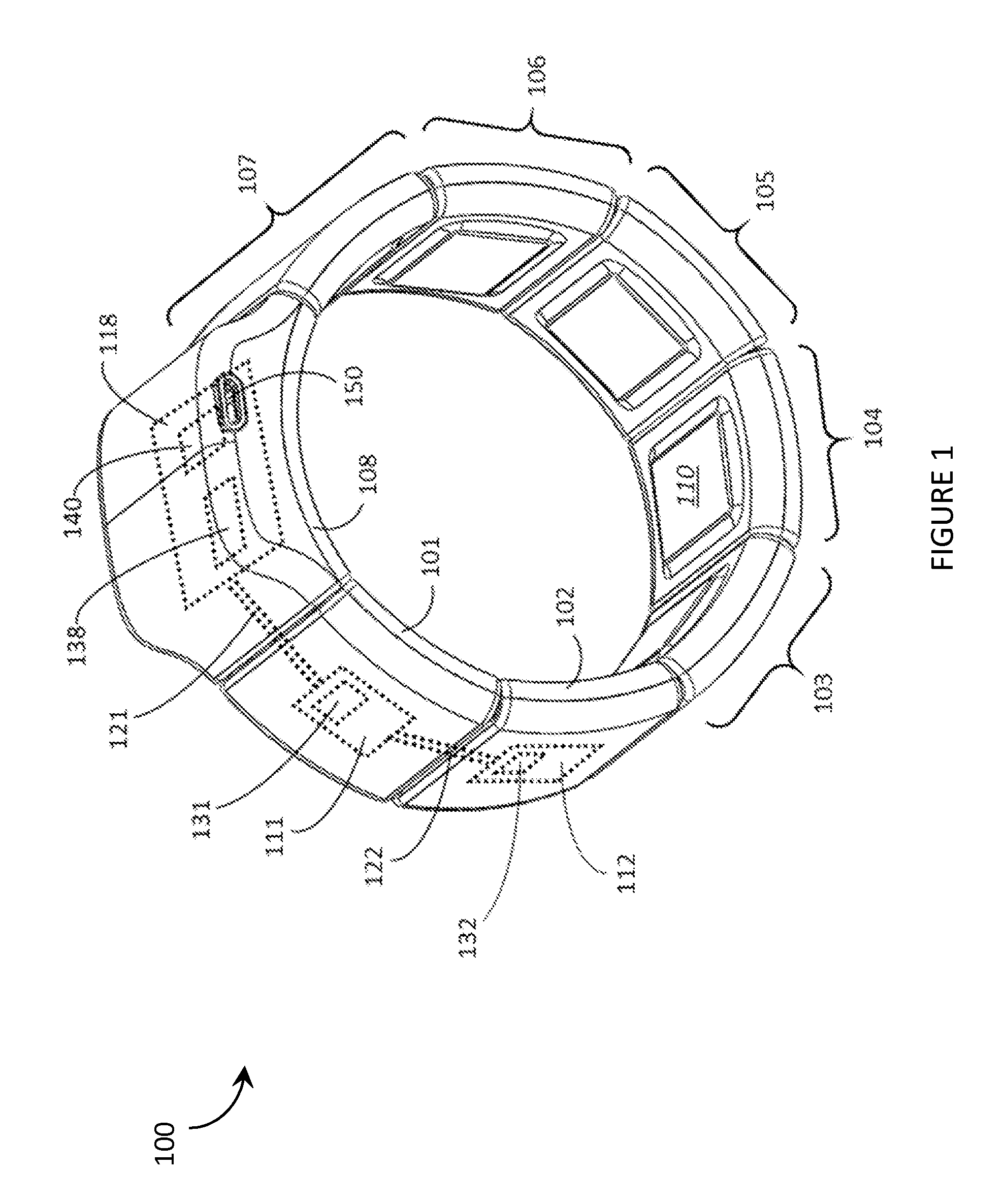
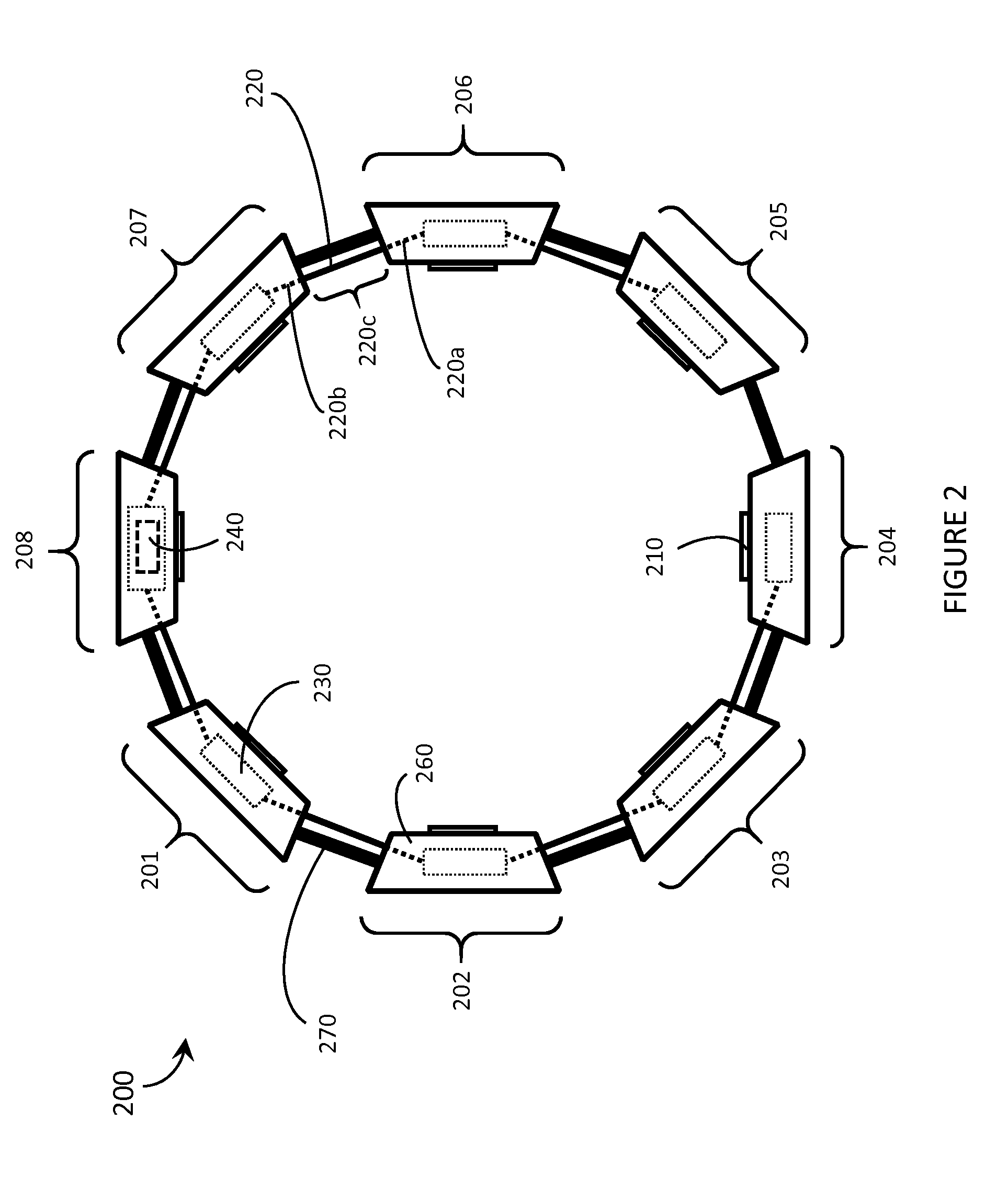
The patent describes a wearable electronic device with a set of pod structures that are physically coupled to each other. The device includes at least two sensor pods and a processor pod. The sensor pods detect inputs from the user and send signals to the processor pod, which then converts the signals into digital signals. The processor pod includes an amplification circuit and an analog-to-digital conversion circuit to process the signals. The device also includes a digital signal bus and a power line / ground line for the processor pod. The sensor pods are positioned on the surface of the device's housing, while the processor pod is positioned inside the housing. The communicative pathways between the pod structures may include electrically conductive paths or optical paths, and may also include flexible printed circuit boards. The technical effects of this design include improved accuracy and efficiency in detecting and processing user inputs, as well as improved wearability and flexibility of the device.

Problems solved by technology

However, the convenience of being able to carry a portable electronic device has also introduced the inconvenience of having one's hand(s) encumbered by the device itself.
Users of wearable electronic devices may desire more sophisticated functionality, but more sophisticated functionality may adversely affect affordability.
Affordability is directly tied to manufacturability, and more sophisticated functionality may necessitate more expensive electric circuitry or manufacturing processes that drive up manufacturing costs.

Method used


Image

  • Systems, articles and methods for signal routing in wearable electronic devices
  • Systems, articles and methods for signal routing in wearable electronic devices
  • Systems, articles and methods for signal routing in wearable electronic devices

Examples


Embodiment Construction

[0035]In the following description, certain specific details are set forth in order to provide a thorough understanding of various disclosed embodiments. However, one skilled in the relevant art will recognize that embodiments may be practiced without one or more of these specific details, or with other methods, components, materials, etc. In other instances, well-known structures associated with electronic devices, and in particular portable electronic devices such as wearable electronic devices, have not been shown or described in detail to avoid unnecessarily obscuring descriptions of the embodiments.

[0036]Unless the context requires otherwise, throughout the specification and claims which follow, the word “comprise” and variations thereof, such as, “comprises” and “comprising” are to be construed in an open, inclusive sense, that is as “including, but not limited to.”

[0037]Reference throughout this specification to “one embodiment” or “an embodiment” means that a particular feat...


PUM


Abstract

Wearable electronic devices that employ techniques for routing signals between components are described. An exemplary wearable electronic device includes a set of pod structures with each pod structure positioned adjacent and physically coupled to at least one other pod structure. The set of pod structures includes multiple sensor pods and at least one processor pod. Each sensor pod includes an on-board sensor to in use detect user-effected inputs and provide signals in response to the user-effected inputs. The signals are serially routed via successive ones of adjacent pod structures by respective communicative pathways until the signals are routed from the sensor pods to the processor pod. A processor on-board the processor pod processes the signals. Systems, articles, and methods for routing electrical signals and / or optical signals, including analog signals and / or digital signals, between pod structures are described.

Description

BACKGROUND[0001]1. Technical Field[0002]The present systems, articles and methods generally relate to wearable electronic devices and particularly relate to systems, articles and methods for signal routing in wearable electronic devices.[0003]2. Description of the Related Art[0004]Wearable Electronic Devices[0005]Electronic devices are commonplace throughout most of the world today. Advancements in integrated circuit technology have enabled the development of electronic devices that are sufficiently small and lightweight to be carried by the user. Such “portable” electronic devices may include on-board power supplies (such as batteries or other power storage systems) and may be designed to operate without any wire-connections to other electronic systems; however, a small and lightweight electronic device may still be considered portable even if it includes a wire-connection to another electronic system. For example, a microphone may be considered a portable electronic device whether...

Claims


Application Information

Patent Timeline
IPC IPC(8): A61B5/00A61B5/04A61B5/0492A61B5/296
CPCA61B5/681A61B5/7475A61B5/04012A61B5/0492A61B5/6898G06F1/163G06F3/015A61B5/389
Inventor BAILEY, MATTHEWLAKE, STEPHENGRANT, AARON
Owner META PLATFORMS TECH LLC
Learn More