Model-Based Neuromechanical Controller For A Robotic Leg
What is Al technical title?
Al technical title is built by PatSnap Al team. It summarizes the technical point description of the patent document.
a neuromechanical controller and robotic leg technology, applied in the field of artificial joints and limbs control, can solve the problems of little attention paid to understanding how such architectures might represent or encode locomotion mechanics principles, passive ankle-foot prostheses cannot provide the capability of terrain adaptation, and raise the issue of control
Active Publication Date: 2015-02-19
MASSACHUSETTS INST OF TECH
View PDF0 Cites 28 Cited by
Summary
Abstract
Description
Claims
Application Information
AI Technical Summary
This helps you quickly interpret patents by identifying the three key elements:
Problems solved by technology
Method used
Benefits of technology
[0020]In one aspect, the present invention is a controller and a control methodology for a biomimetic robotic leg based on a neuromuscular model of human locomotion. The control architecture commands biomimetic torques at the ankle, knee, and hip joints of a powered leg prosthesis, orthosis, or exoskeleton during walking In a preferred embodiment, the powered device includes artificial ankle and knee joints that are torque controllable. Appropriate joint torques are provided to the user as determined by the feedback information provided by sensors mounted at each joint of the robotic leg device. These sensors include, but are not limited to, angular joint displacement and velocity using digital encoders, hall-effect sensors or the like, torque sensors at the ankle and knee joints, and at least one inertial measurement unit (IMU) located between the knee and the ankle joints.
[0021]Sensory information of joint state (position and velocity) from the robotic leg is used as inputs to a neuromuscular model of human locomotion. Joint state sensory information from the robotic leg is used to determine the internal state for each of its virtual muscles, and what the individual virtual muscle force and stiffness should be given particular levels of muscle activation is determined from a spinal reflex model. If the robotic leg is a leg prosthesis worn by a transfemoral amputee, angular sensors at the ankle and knee measure joint state for these joints. For the hip joint, the absolute orientation of the user's thigh is determined using both the angular joint sensor at the prosthetic knee and an IMU positioned between the prosthetic knee and the ankle joints. To estimate hip position and velocity, the control architecture works under the assumption that the upper body (torso) maintains a relative vertical position during gait.
[0022]In one aspect, the invention is a model-based neuromechanical controller for a robotic limb comprising at least one joint, the controller comprising a neuromuscular model including a muscle model, muscle tendon lever arm and muscle tendon length equations and reflect control equations, the neuromuscular model being configured to receive feedback data relating to a measured state of the robotic limb and, using the feedback data, and the muscle model, muscle tendon lever arm and muscle tendon length equations and reflect control equations of the neuromuscular model, to determine at least one torque command, the controller further comprising a torque control system in communication with the neuromuscular model, whereby the torque control system receives the at least one torque command from the neuromuscular model for controlling the robotic limb joint. In a preferred embodiment, the feedback data is provided by at least one sensor mounted at each joint of the robotic limb. In another preferred embodiment, the robotic limb is a leg and the controller further includes a finite state machine synchronized to the leg gait cycle, the finite state machine being configured to receive the feedback data from the at least one sensor to determine a gait phase of the robotic leg using the feedback data received.
[0023]In another aspect, the invention is a model-based method for controlling a robotic limb comprising at least one joint, comprising the steps of receiving feedback data relating to the state of the robotic limb at a finite state machine, determining the state of the robotic limb using the finite state machine and the received feedback data, determining, using a neuromuscular model that includes muscle tendon lever arm and muscle tendon length equations and reflex control equations, and state information from the finite state machine, at least one desired joint torque or stiffness command to be sent to the robotic limb and commanding the biomimetic torques and stiffnesses determined by the muscle model processor at the robotic limb joint.
Problems solved by technology
However, little attention has been paid to understanding how such architectures might represent or encode principles of locomotion mechanics.
Passive ankle-foot prostheses cannot provide the capability of adaptation to terrain.
The use of active motor power in these prostheses raises the issue of control.
However, this control approach exhibited no inherent adaptation.
In general, existing commercially available active ankle prostheses are only able to reconfigure the ankle joint angle during the swing phase, requiring several strides to converge to a terrain-appropriate ankle position at first ground contact.
Further, they do not provide any of the stance phase power necessary for normal gait, and therefore cannot adapt net stance work with terrain slope.
Although effective at their intended gait speed and terrain, these controllers do not allow for adaptation to environmental disturbances such as speed transients and terrain variation.
Method used
Image
Click on the blue label to locate the original text in one second.
Reading with bidirectional positioning of images and text.
Examples
Embodiment Construction
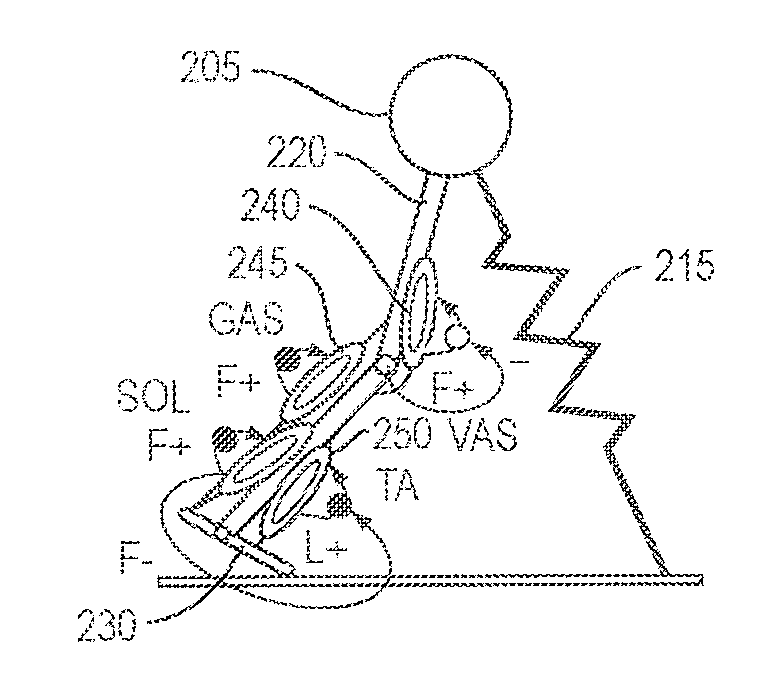
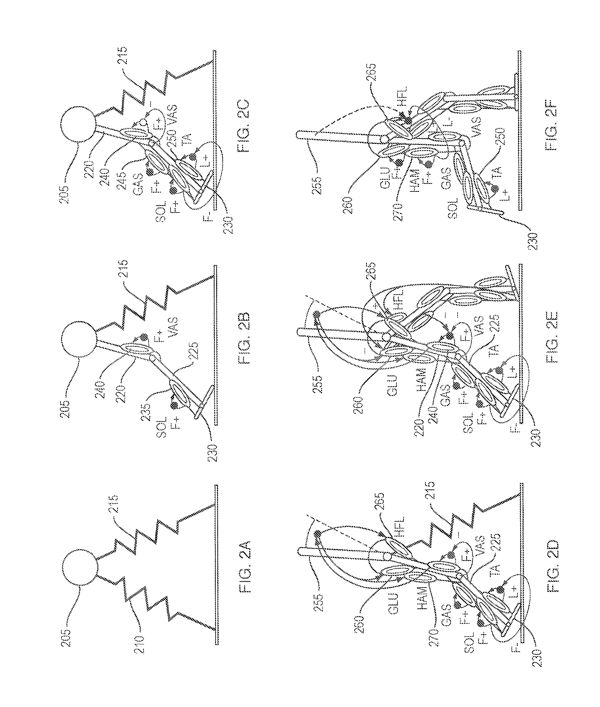
[0043]A control architecture is presented to command biomimetic torques at the ankle, knee, and hip joints of a powered leg prosthesis, orthosis, or exoskeleton during walking. In this embodiment, the powered device includes artificial ankle and knee joints that are torque controllable. Appropriate joint torques are provided to the user as determined by the feedback information provided by sensors mounted at each joint of the robotic leg device. These sensors include, but are not limited to, angular joint displacement and velocity using digital encoders, hall-effect sensors or the like, torque sensors at the ankle and knee joints and at least one inertial measurement unit (IMU) located between the knee and the ankle joints.
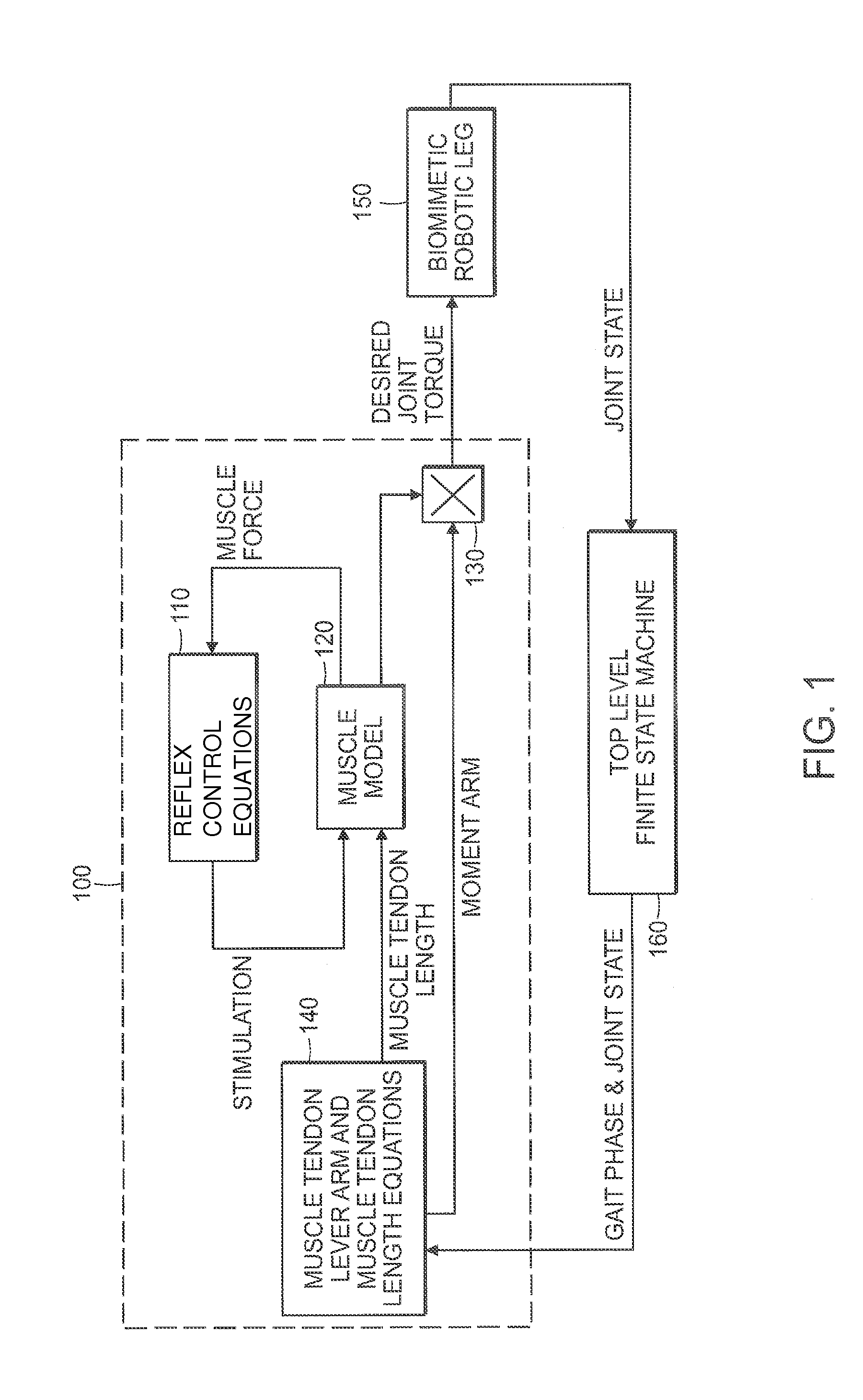
[0044]Sensory information of joint state (position and velocity) from the robotic leg (hip, knee and ankle) is used as inputs to a neuromuscular model of human locomotion. This model uses joint state sensory information from the robotic leg to determine the intern...
PUM
Abstract
A model-based neuromechanical controller for a robotic limb having at least one joint includes a finite state machine configured to receive feedback data relating to the state of the robotic limb and to determine the state of the robotic limb, a muscle model processor configured to receive state information from the finite state machine and, using muscle geometry and reflex architecture information and a neuromuscular model, to determine at least one desired joint torque or stiffness command to be sent to the robotic limb, and a joint command processor configured to command the biomimetic torques and stiffnesses determined by the muscle model processor at the robotic limb joint. The feedback data is preferably provided by at least one sensor mounted at each joint of the robotic limb. In a preferred embodiment, the robotic limb is a leg and the finite state machine is synchronized to the leg gait cycle.
Description
RELATED APPLICATIONS[0001]This Application is a divisional of U.S. patent application Ser. No. 12 / 698,128, filed Feb. 1, 2010, now U.S. Pat. No. 8,864,846, which claims the benefit of U.S. Provisional Patent Appl. Ser. No. 61 / 148,545, filed Jan. 30, 2009, and is a continuation-in-part of U.S. patent application Ser. No. 12 / 608,627, filed Oct. 29, 2009, now U.S. Pat. No. 8,870,967, which is a continuation of U.S. patent application Ser. No. 11 / 642,993, filed Dec. 19, 2006, now abandoned, which claims the benefit of the U.S. Provisional Patent Appl. Ser. No. 60 / 751,680, filed Dec. 19, 2005, and is a continuation-in-part of U.S. patent application Ser. No. 11 / 600,291, filed Nov. 15, 2006, now abandoned, which claims the benefit of U.S. Provisional Appl. No. 60 / 736,929, filed Nov. 15, 2005 and U.S. Provisional Appl. No. 60 / 705,651, filed Aug. 4, 2005, and is a continuation-in-part of U.S. patent application Ser. No. 11 / 395,448, filed Mar. 31, 2006, which claims the benefit of U.S. Provi...
Claims
Application Information
Patent Timeline
Application Date:The date an application was filed.
Publication Date:The date a patent or application was officially published.
First Publication Date:The earliest publication date of a patent with the same application number.
Issue Date:Publication date of the patent grant document.
PCT Entry Date:The Entry date of PCT National Phase.
Estimated Expiry Date:The statutory expiry date of a patent right according to the Patent Law, and it is the longest term of protection that the patent right can achieve without the termination of the patent right due to other reasons(Term extension factor has been taken into account ).
Invalid Date:Actual expiry date is based on effective date or publication date of legal transaction data of invalid patent.
Patent Type & Authority Applications(United States)