
Apparatus and process for fluid catalytic cracking

a technology of fluid catalytic cracking and apparatus, which is applied in the direction of liquid-gas reaction process, chemical/physical/physicochemical stationary reactor, petroleum industry, etc., can solve the problem of deteriorating the diameter distribution of catalyst in the downflow reactor, and achieve the effect of high compactness

Active Publication Date: 2015-02-26
INDIAN OIL CORPORATION
View PDF0 Cites 0 Cited by
  • Summary
  • Abstract
  • Description
  • Claims
  • Application Information

AI Technical Summary

Benefits of technology

The invention aims to improve the contact between circulating catalyst and hydrocarbon feed in a compact way. The proposed hardware includes a radial distributor that evenly distributes catalyst into the reactor. This distributor has stationary and movable parts placed one after another to cover the entire opening at the inlet of the reactor. The distributor is placed concentric with the regenerator and located between the regenerated catalyst holding vessel and the reactor. This technical effect ensures efficient and effective contact between the catalyst and the hydrocarbon feed.

Problems solved by technology

Although the downflow reactor is said to have superior flow characteristics in comparison to the riser, the main challenge remains the distribution of the catalyst at the initial section of the down flow reactor where it is contacted with hot hydrocarbon feed.
Moreover, the radial distribution of the catalyst in a downflow reactor deteriorates with increase in diameter.
This technique suffers from the solids flow control through the pressure difference.

Method used


Image

  • Apparatus and process for fluid catalytic cracking
  • Apparatus and process for fluid catalytic cracking
  • Apparatus and process for fluid catalytic cracking

Examples


Embodiment Construction

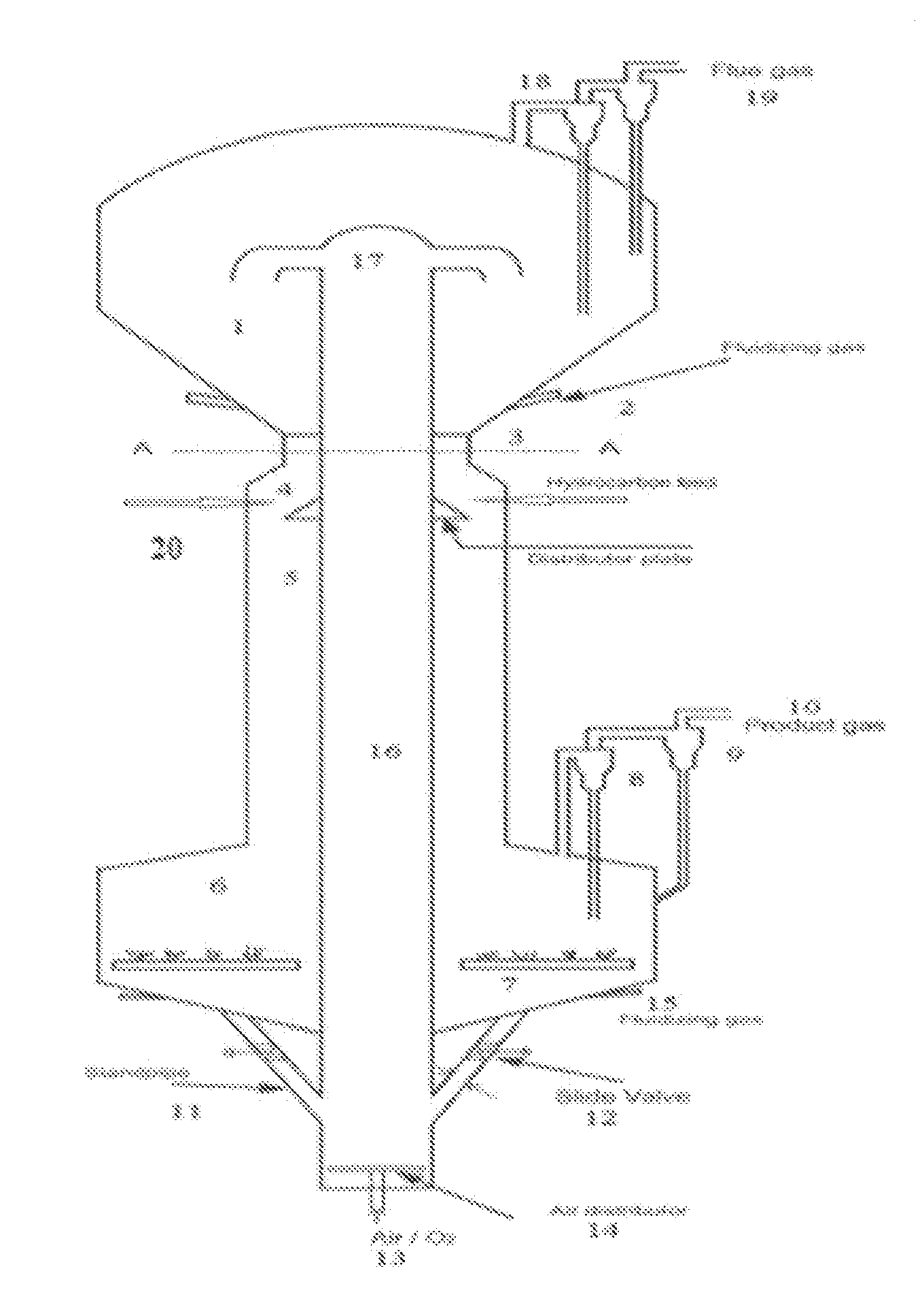
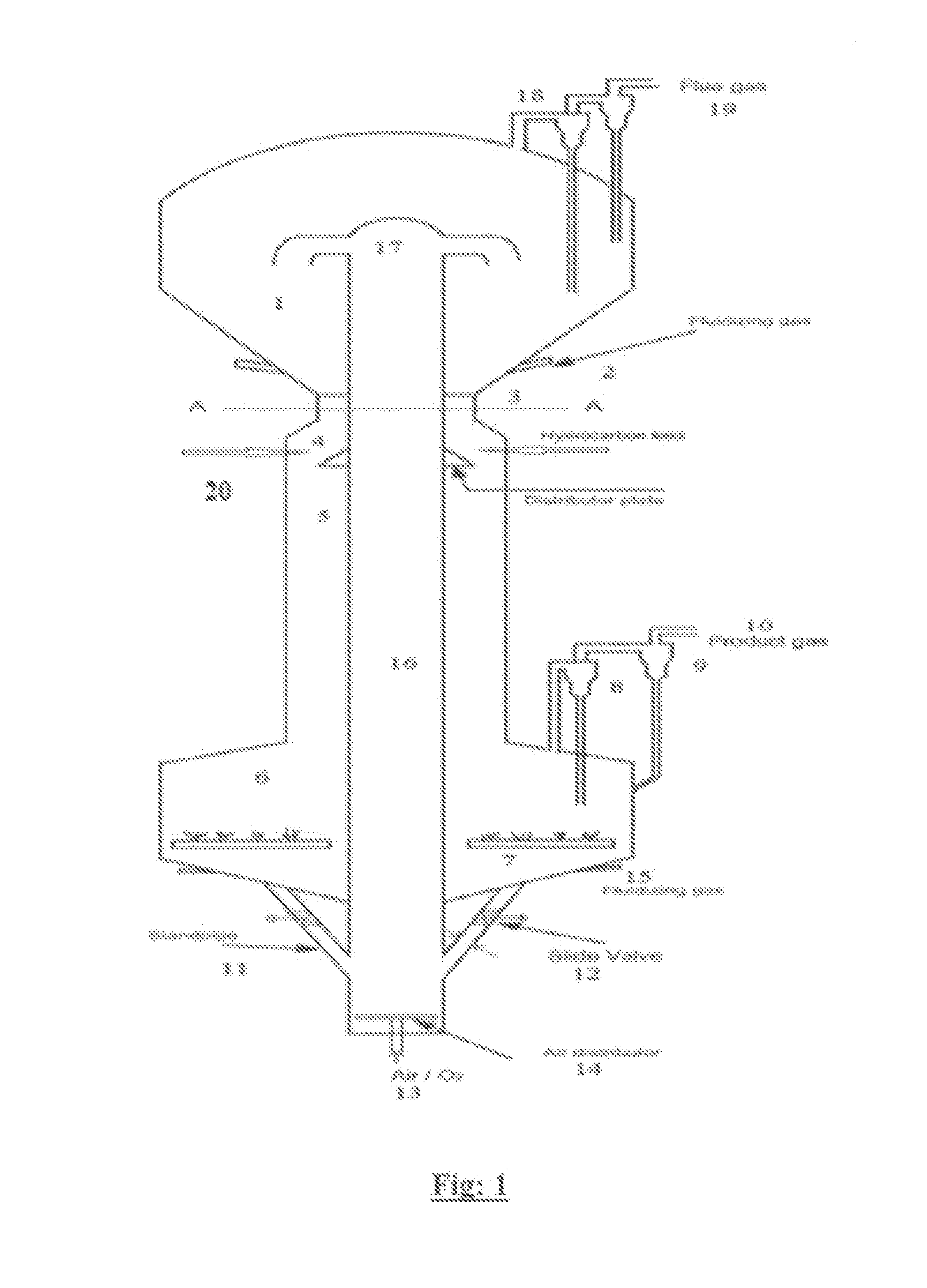
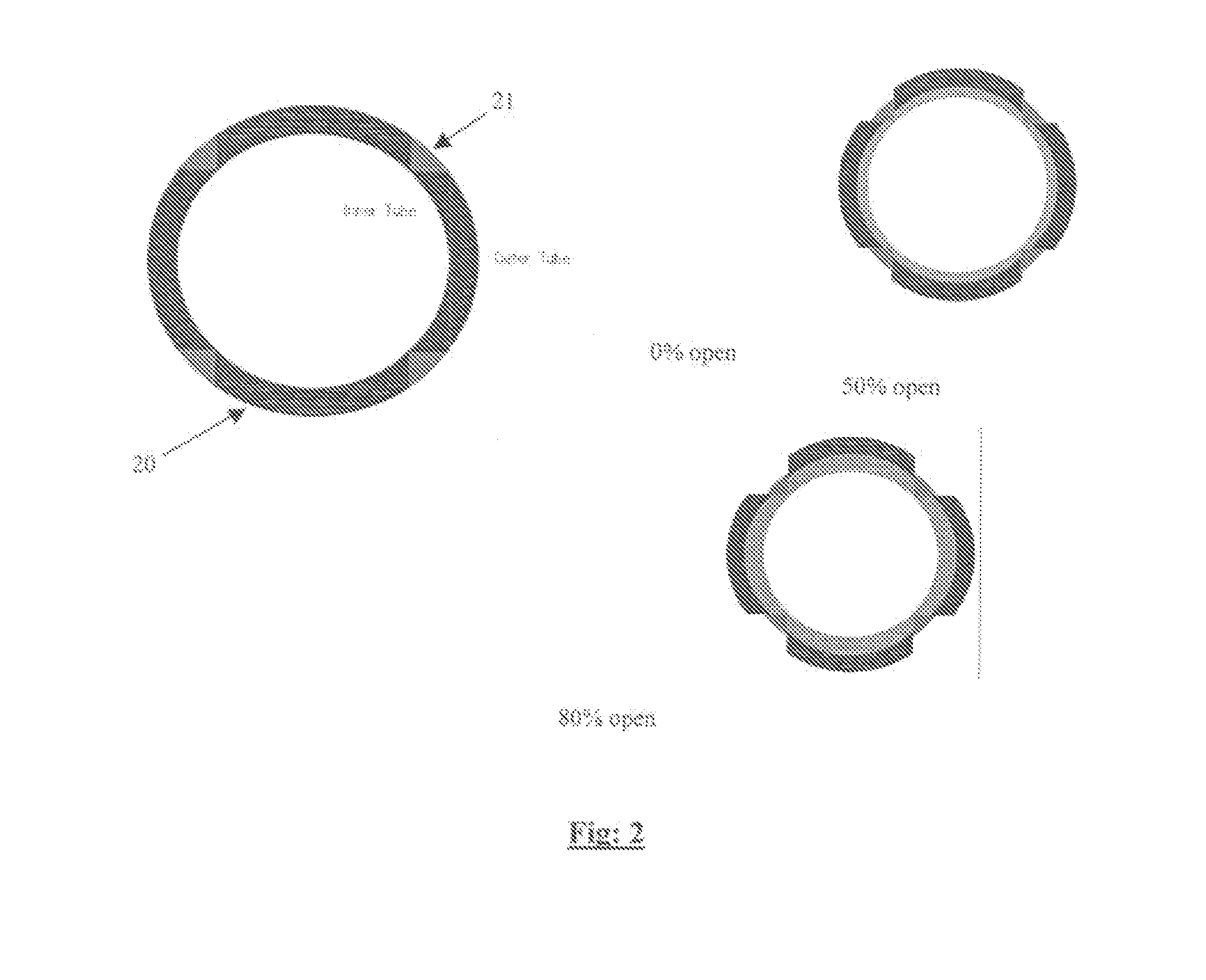
[0021]The proposed apparatus is an integral hardware consisting of an annular downer reactor and an upflow riser regenerator for catalytic cracking of hydrocarbon feed to valuable lighter products. The advantage of this configuration is that its design is highly compact and provides efficient contact between circulating catalyst and hydrocarbon feed. The schematic of the apparatus is given in FIG. 1. The radial distribution of the catalyst in a downflow reactor deteriorates as the diameter increases. To mitigate this, annular curtain flow design with the novel radial distributor for providing improved radial distribution of catalyst into the annular downer reactor is proposed. The schematic of the radial distributor is given in FIG. 2.

The Apparatus

[0022]The apparatus according to this invention for fluid catalytic cracking comprising of reactor, regenerator and stripper is described in a sequential manner below. The apparatus is best seen in FIG. 1.

[0023]An annular downer reactor (5...


PUM


Abstract

An apparatus which is an integral hardware consisting of an annular downer reactor and a concentric upflow riser regenerator for catalytic cracking of hydrocarbon feed to is disclosed. The annular downer reactor terminates in annular stripper which is also concentric with the regenerator. The regenerator, reactor and stripper are in fluid connection with each other. The apparatus is highly compact and provides efficient contact between circulating catalyst and hydrocarbon feed. The proposed hardware includes a novel radial distributor for providing improved control and radial distribution of catalyst inside the downflow reactor. The radial distributor has equal numbers of stationary and movable parts placed one after another to cover the entire annular opening at the bottom of the regenerated catalyst vessel. The radial distributor is concentric with regenerator and located between the catalyst holding vessel and the reactor. A process for catalytic cracking using the invented apparatus is also disclosed.

Description

FIELD OF THE INVENTION[0001]The present invention relates to an improved process and an apparatus for catalytic cracking of hydrocarbon feed for production of valuable lighter products. More particularly, it relates to a fluid catalytic cracking process and apparatus employing an annular downer reactor equiped with a novel design of catalyst distributor to provide efficient contact between the circulating catalyst and the hydrocarbon feed.BACKGROUND AND PRIOR ART OF THE INVENTION[0002]Fluid Catalytic Cracking (FCC) is one of the most important secondary conversion processes to convert the high-boiling, high-molecular weight hydrocarbon fractions to valuable products such as LPG, gasoline, and middle distillates. This process provides flexibility to maximize the product of interest through operation under different modes.[0003]The conversion section of FCC unit consists of riser, reactor, stripper, regenerator and hardware internals. As the price of petroleum crudes has been increasi...

Claims


Application Information

Patent Timeline
IPC IPC(8): B01J19/24C10G11/10
CPCC10G11/10B01J19/24B01J8/26B01J8/386B01J2208/0084C10G11/18
Inventor SADHULLAH, MUKTHIYARKUMARAN, SATHEESH VETTERKUNNELBHATTACHARYYA, DEBASISSAIDULU, GADARIKUKADE, SOMNATHKUMAR, BRIJESHRAJAGOPAL, SANTANAM
Owner INDIAN OIL CORPORATION
Learn More