Noise-shielded capacitive touch device

a capacitive touch, shielded technology, applied in the direction of resistance/reactance/impedence, instruments, optics, etc., can solve the problem of significant enlargement of the device, and achieve the effect of avoiding cross interferen

Active Publication Date: 2015-02-26
PIXART IMAGING INC
View PDF1 Cites 3 Cited by
  • Summary
  • Abstract
  • Description
  • Claims
  • Application Information

AI Technical Summary

Benefits of technology

[0015]From another perspective, the present invention provides a noise-shielded capacitive touch device, comprising: a substrate; a first sensor region, including: a plurality of first sensing lines disposed at a first side of the substrate, which are in parallel with each other and extend along a first direction; and a plurality of first driving lines disposed at a second side of the substrate, which are in parallel with each other and extend along a second direction, wherein the second side is opposite to the first side, and the second direction intersect with the first direction, and wherein the plurality of first sensing lines intersect with the plurality of first driving lines from a top view; a second sensor region, including: a plurality of second sensing lines disposed at a first side of the substrate, which are in parallel with each other and extend along a first direction; and a plurality of second driving lines disposed at a second side of the substrate, which are in parallel with each other and extend along a second direction, wherein the second side is opposite to the first side, and the second direction intersect with the first direction, and wherein the plurality of second sensing lines intersect with the plurality of second driving lines from a top view; and an electric field wall between the first sensor region and the second sensor region for isolating the first sensor region and the second sensor region to avoid cross interferences between the first sensor region and the second sensor region.

Problems solved by technology

Nevertheless, this solution requires a great modification of the layout and it significantly enlarges the size of the device.

Method used


Image

  • Noise-shielded capacitive touch device
  • Noise-shielded capacitive touch device
  • Noise-shielded capacitive touch device

Examples


Embodiment Construction

[0024]The above and other technical details, features and effects of the present invention will be will be better understood with regard to the detailed description of the embodiments below, with reference to the drawings. In the description, the words relate to directions such as “upper”, “lower”, “left”, “right”, “forward”, “backward”, etc. are used to illustrate relative orientations in the drawings and should not be considered as limiting in any way. The drawings as referred to throughout the description of the present invention are for illustration only, to show the interrelations between the apparatus and the devices, but not drawn according to actual scale.

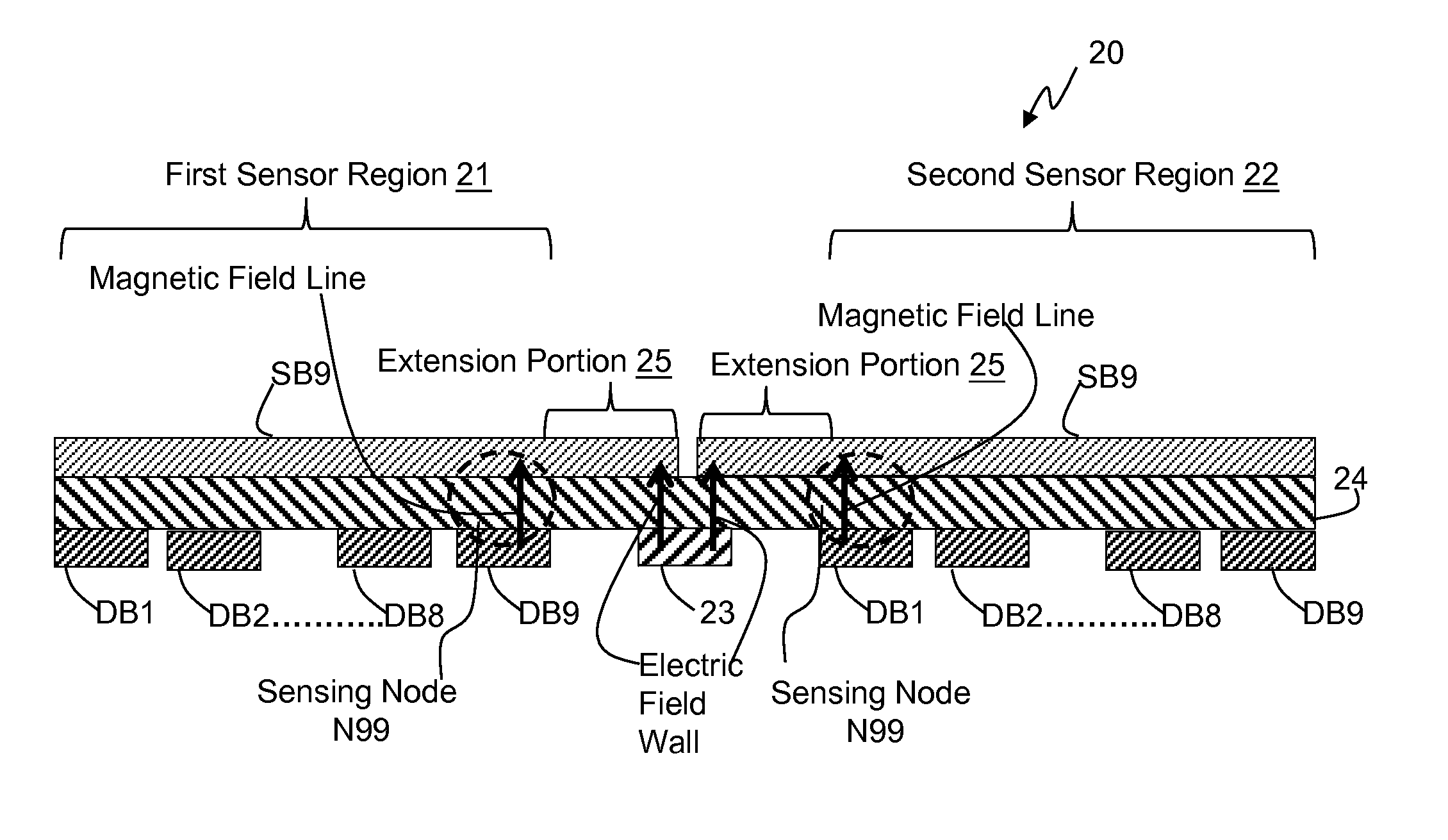
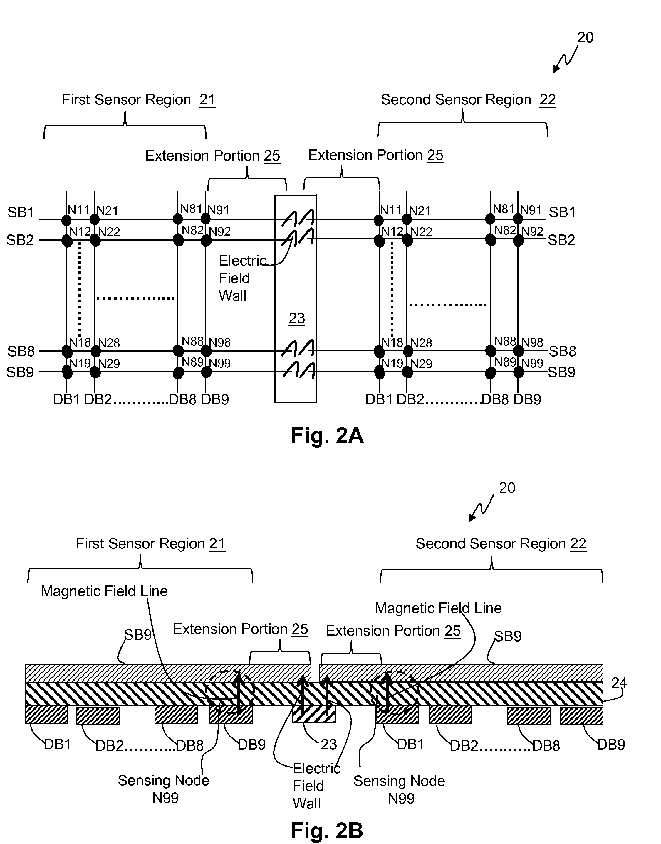
[0025]Please refer to FIG. 2A, which shows a top view of a noise-shielded capacitive touch device according to an embodiment of the present invention. The noise-shielded capacitive touch device 20 shown in FIG. 2A can be, for example, a mutual capacitance type touch panel. The noise-shielded capacitive touch device 20 compr...


PUM


Abstract

The present invention discloses a noise-shielded capacitive touch device, which includes a first sensor region, a second sensor region and a shielding layer. Each of the first sensor region and the second sensor region includes plural sensing lines and driving lines. The sensing lines are in parallel with each other and extend along a first direction. Each sensing line has an extension portion at its end near the other sensor region. The driving lines are in parallel with each other and extend along a second direction, wherein the second direction intersects the first direction. The extension portions and the shielding layer form an electric field wall to avoid cross interferences between the two sensor regions.

Description

CROSS REFERENCE[0001]The present invention claims priority to TW102130285, filed on Aug. 23, 2013.BACKGROUND OF THE INVENTION[0002]1. Field of Invention[0003]The present invention relates to a noise-shielded capacitive touch device; particularly, it relates to such noise-shielded capacitive touch device capable of effectively isolating two sensor regions to avoid cross interferences.[0004]2. Description of Related Art[0005]Please refer to FIG. 1A, which shows a top view of a conventional capacitive touch device. The conventional capacitive touch device 10 shown in FIG. 1A is for example a mutual capacitance type touch panel which comprises multiple sensor regions. In the shown example, the capacitive touch device 10 comprises a first sensor region 11 and a second sensor region 12, wherein each of the first sensor region 11 and the second sensor region 12 is, for example, a capacitive touch sensor. Each of the first sensor region 11 and the second sensor region 12 includes plural dri...

Claims


Application Information

Patent Timeline
Patent Type & Authority Applications(United States)
IPC IPC(8): G01R1/18G01R27/26
CPCG01R27/2605G01R1/18G06F3/0445G06F3/0446G06F2203/04107
Inventor YANG, KUAN-YI
Owner PIXART IMAGING INC
Why Eureka
Try Eureka