Liquid crystal display panel

a liquid crystal display and panel technology, applied in non-linear optics, instruments, optics, etc., can solve the problems of poor display quality of the lcd panel, and achieve the effect of improving the display quality and improving the unbalance domain area of unsatisfactory optical expression of the side view

Inactive Publication Date: 2015-02-26
INNOLUX CORP
View PDF5 Cites 9 Cited by
  • Summary
  • Abstract
  • Description
  • Claims
  • Application Information

AI Technical Summary

Benefits of technology

[0026]As mentioned above, in the LCD panel of the invention, a plurality of pixel units are arranged in a matrix formed by columns and rows, and each pixel unit is divided into a plurality of domains. Besides, the alignment direction of the first alignment layer is parallel to the column direction, while the alignment direction of the second alignment layer is parallel to the row direction. The domains of the pixel units have different tilt directions for liquid crystal molecules defined by the first and second alignment layers. The domains adjacent to a boundary between the two adjacent pixel units arranged in the row direction have the same tilt direction for liquid crystal molecules defined by the first and second alignment layers. For the entire LCD panel, the unbalance of domain areas in the pixel units caused by shift or misalignment issue can be sufficiently solved due to the self-compensation of all pixel units. Consequently, the unsatisfied optical expression of side view caused by the unbalance domain areas can be improved, thereby providing the LCD panel with better display quality.

Problems solved by technology

However, if the CF substrate and the TFT substrate have shift and misalignment issues during the assembling process, the poor display quality of the LCD panel is deserved.

Method used


Image

  • Liquid crystal display panel
  • Liquid crystal display panel
  • Liquid crystal display panel

Examples


Embodiment Construction

[0038]The present invention will be apparent from the following detailed description, which proceeds with reference to the accompanying drawings, wherein the same references relate to the same elements.

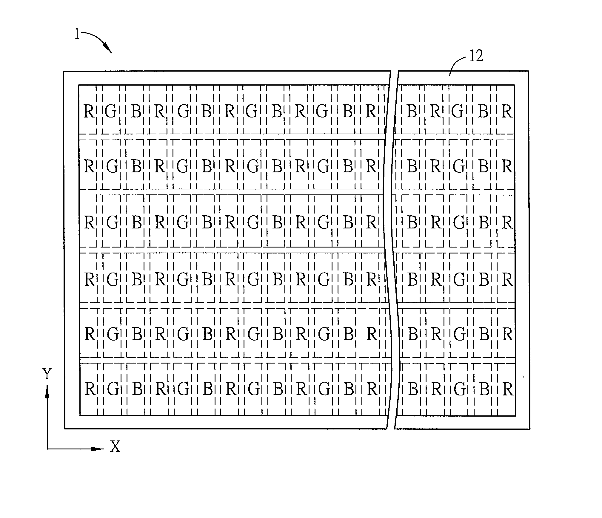
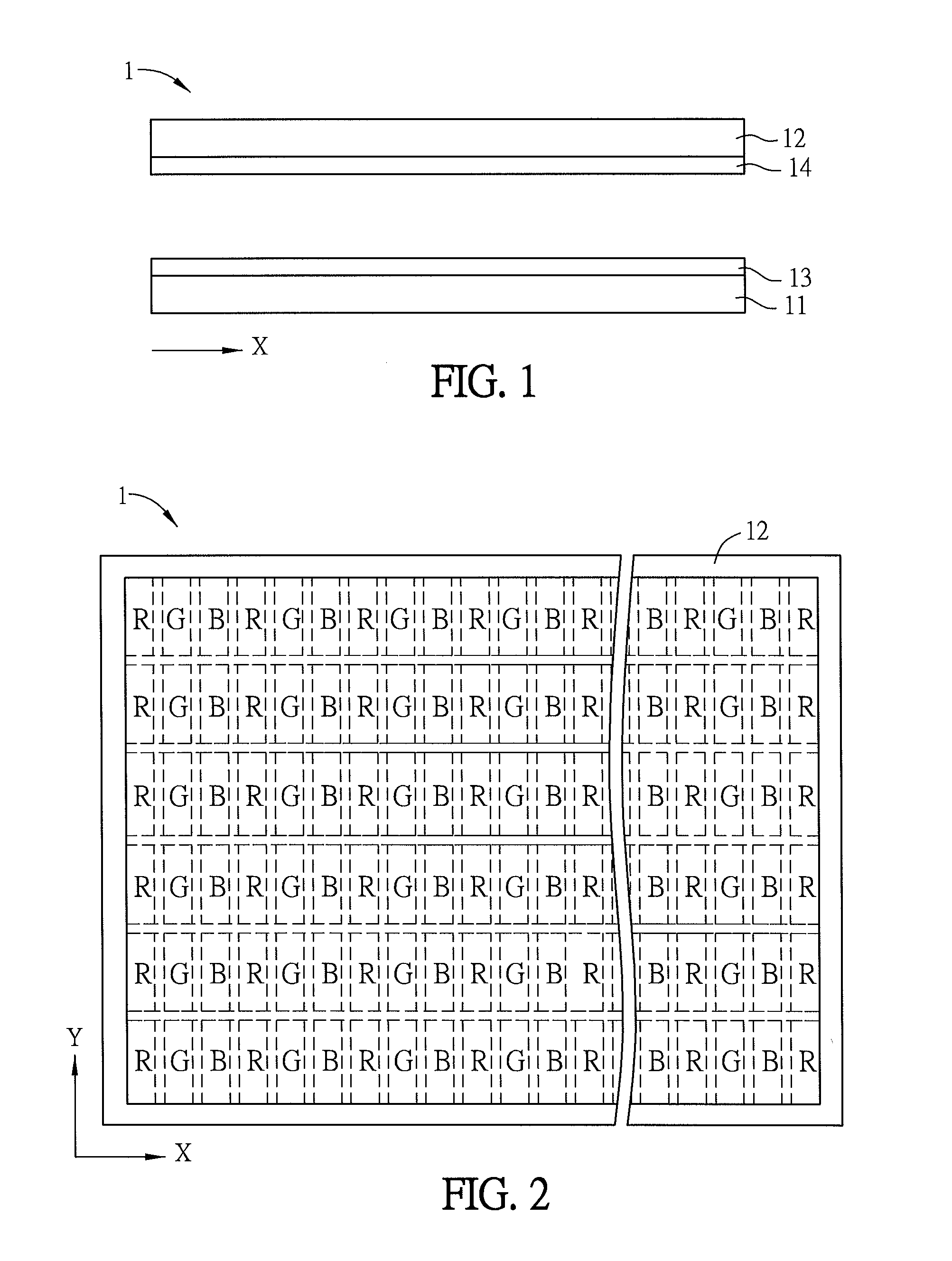
[0039]FIG. 1 is a side view of a liquid crystal display (LCD) panel 1 according to a preferred embodiment of the invention, and FIG. 2 is a top view of the LCD panel 1 of FIG. 1.

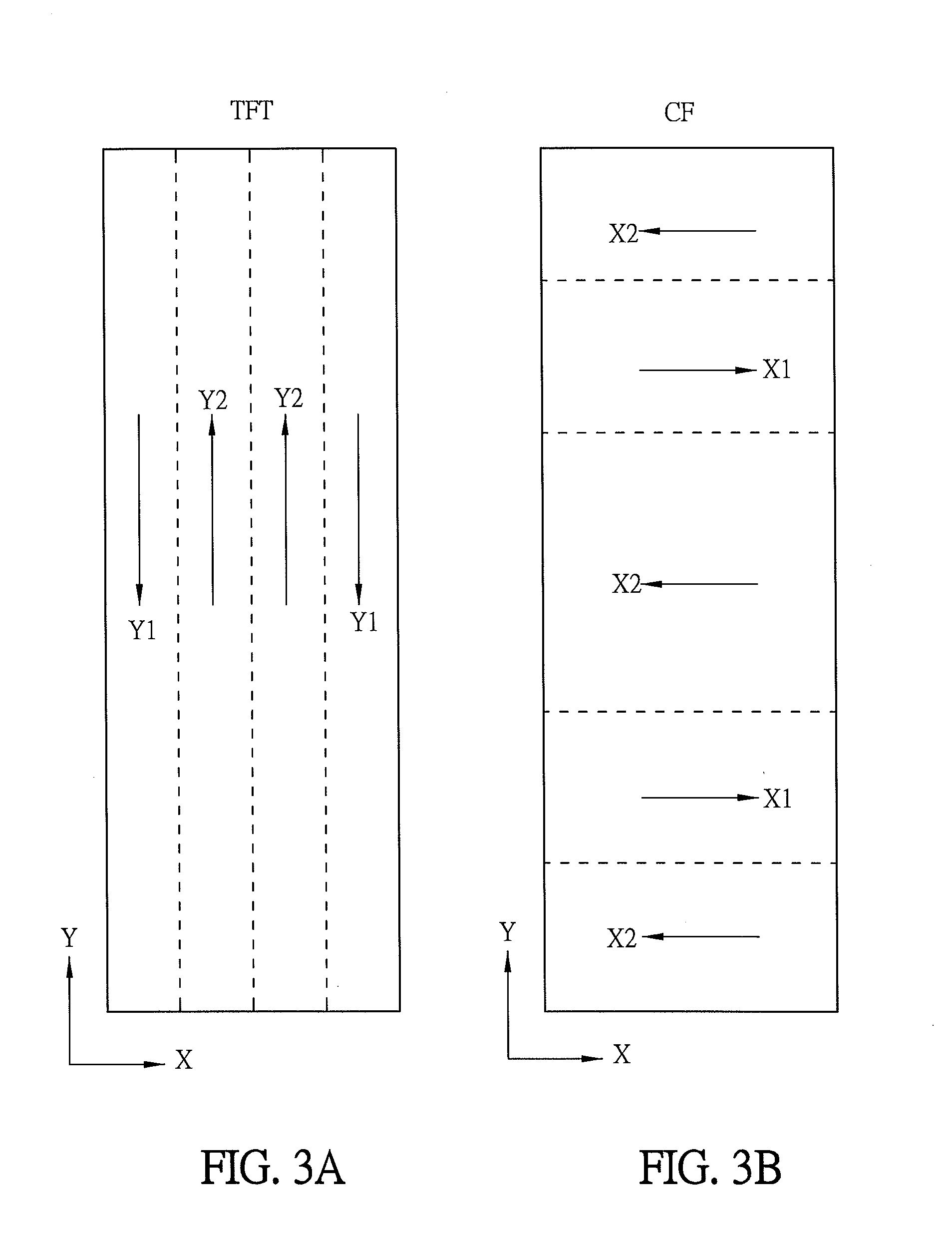
[0040]Referring to FIGS. 1 and 2, the LCD panel 1 includes a first substrate 11, a second substrate 12 and a liquid crystal layer (not shown) including a plurality of liquid crystal molecules. The liquid crystal layer is sandwiched between the first substrate 11 and the second substrate 12, and the first substrate 11, the second substrate 12 and the liquid crystal layer form a plurality of pixel units. The pixel units are configured in a matrix formed by columns and rows, and each pixel unit is divided into a plurality of domains (multi-domain). The domains in each pixel unit are similarly configured in a matr...


PUM

PropertyMeasurementUnit
curvature radiusaaaaaaaaaa

Abstract

A liquid crystal display (LCD) panel includes a plurality of pixel units, a first alignment layer and a second alignment layer. The pixel units are configured in a matrix formed by columns and rows, and each pixel unit is divided into a plurality of domains. The alignment direction of the first alignment layer is parallel to the column direction, while the alignment direction of the second alignment layer is parallel to the row direction. The domains of the pixel units have different tilt directions for liquid crystal molecules defined by the first and second alignment layers. In two adjacent pixel units arranged in the row direction, the domains adjacent to a boundary between the two adjacent pixel units have the same tilt direction for liquid crystal molecules defined by the first and second alignment layers.

Description

CROSS REFERENCE TO RELATED APPLICATIONS[0001]The non-provisional patent application claims priority to U.S. provisional patent application with Ser. No. 61 / 869,304 filed on Aug. 23, 2013 and under 35 U.S.C. §119(a) on Patent Application No(s). 102142038 filed in Taiwan, Republic of China on Nov. 19, 2013. This and all other extrinsic materials discussed herein are incorporated by reference in their entirety.BACKGROUND OF THE INVENTION[0002]1. Field of Invention[0003]The present invention relates to a liquid crystal display (LCD) panel and, in particular, to an LCD panel having multi-domains alignments.[0004]2. Related Art[0005]With the progress of technologies, display devices have been widely applied to various kinds of fields. Especially, liquid crystal display (LCD) devices, having advantages such as compact structure, low power consumption, less weight and less radiation, gradually take the place of cathode ray tube (CRT) display devices, and are widely applied to various electr...

Claims


Application Information

Patent Timeline
Patent Type & Authority Applications(United States)
IPC IPC(8): G02F1/1337G02F1/1343
CPCG02F1/1337G02F1/133788G02F1/134336G02F1/133753G02F1/133757
Inventor TSUEI, BO-CHINCHEN, JIAN-CHENGHSIEH, CHIH-YUNG
Owner INNOLUX CORP
Why Eureka
Try Eureka