

Test apparatus
- Summary
- Abstract
- Description
- Claims
- Application Information
AI Technical Summary
Benefits of technology
Problems solved by technology
Method used
Image

Examples
first embodiment
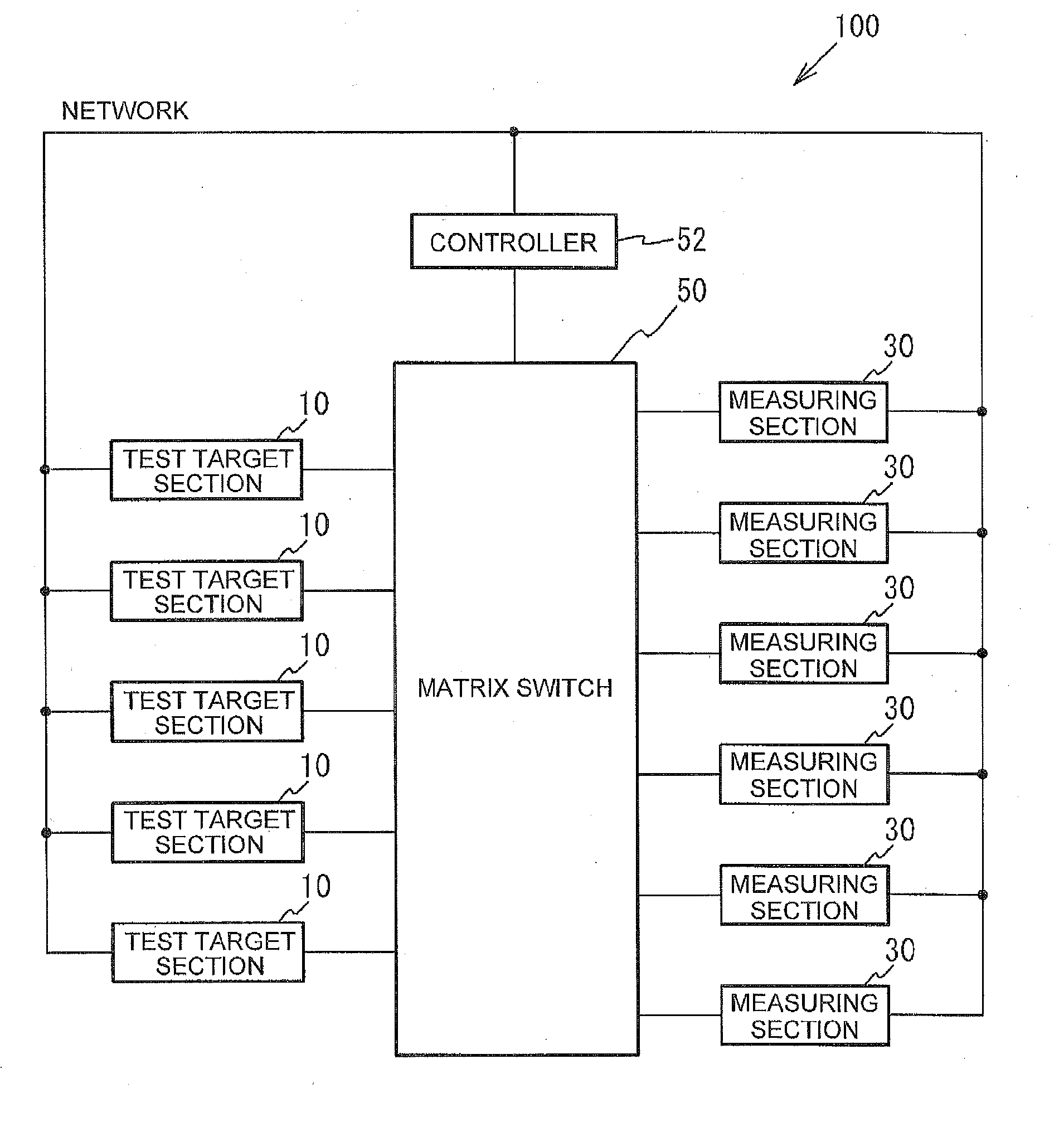
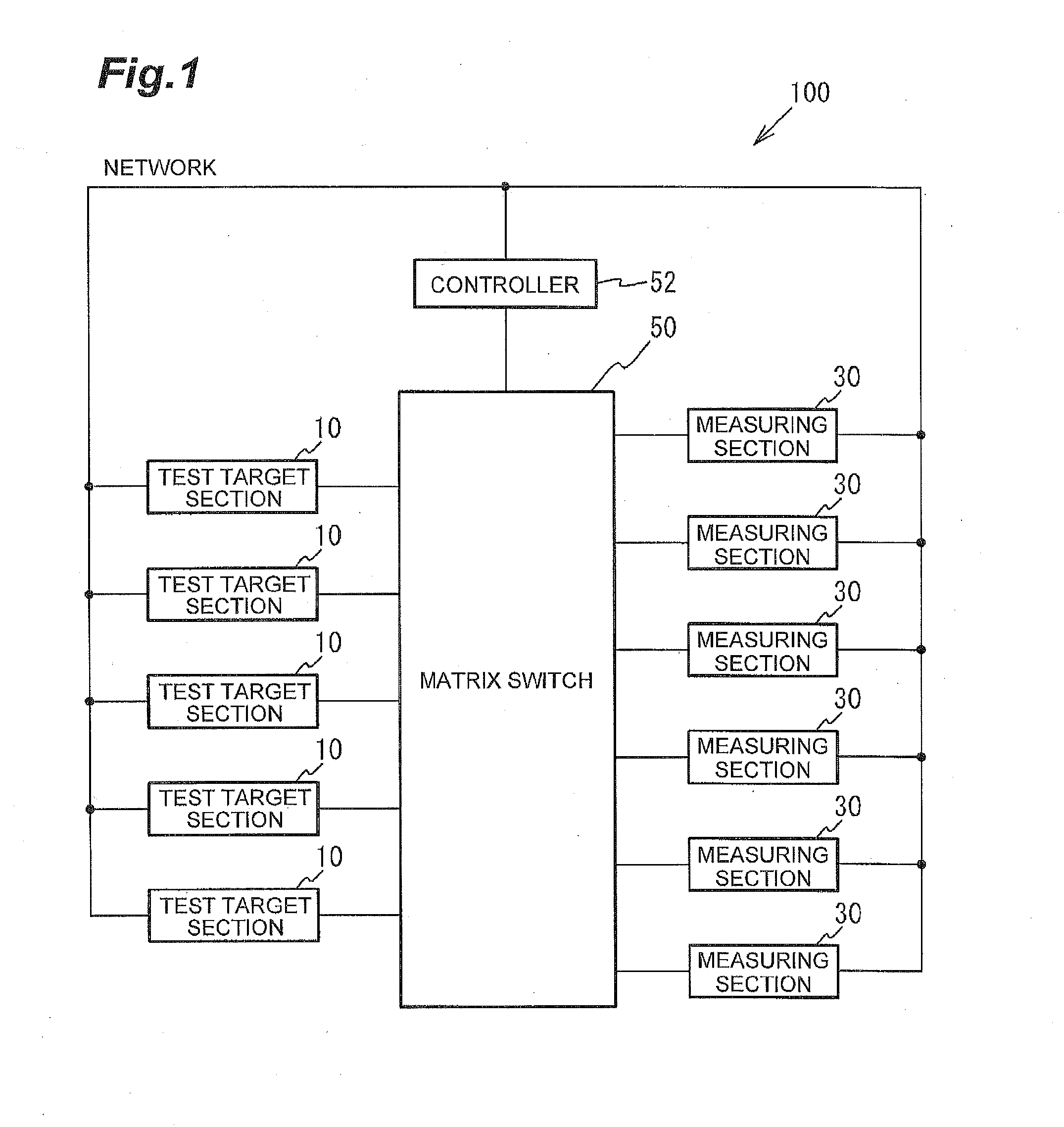
[0034]FIG. 1 is a block diagram illustrating an entire configuration of a test apparatus according to a first embodiment. As shown in FIG. 1, a test apparatus 100 according to the first embodiment includes plural test target sections 10, plural measuring sections 30, a switch section 50, and a controller 52. The switch section 50 is a matrix switch, for example. The matrix switch switches connection between the plurality of test target sections 10 and the plurality of measuring sections 30. The controller 52 includes a central processing unit (CPU), a read-only memory (ROM), a random access memory (RAM), and the like, and controls the switch section 50. The switch section 50 performs switching of connection between the plural test target sections 10 and the plural measuring sections 30 according to a command of the controller 52 to change a connection combination.
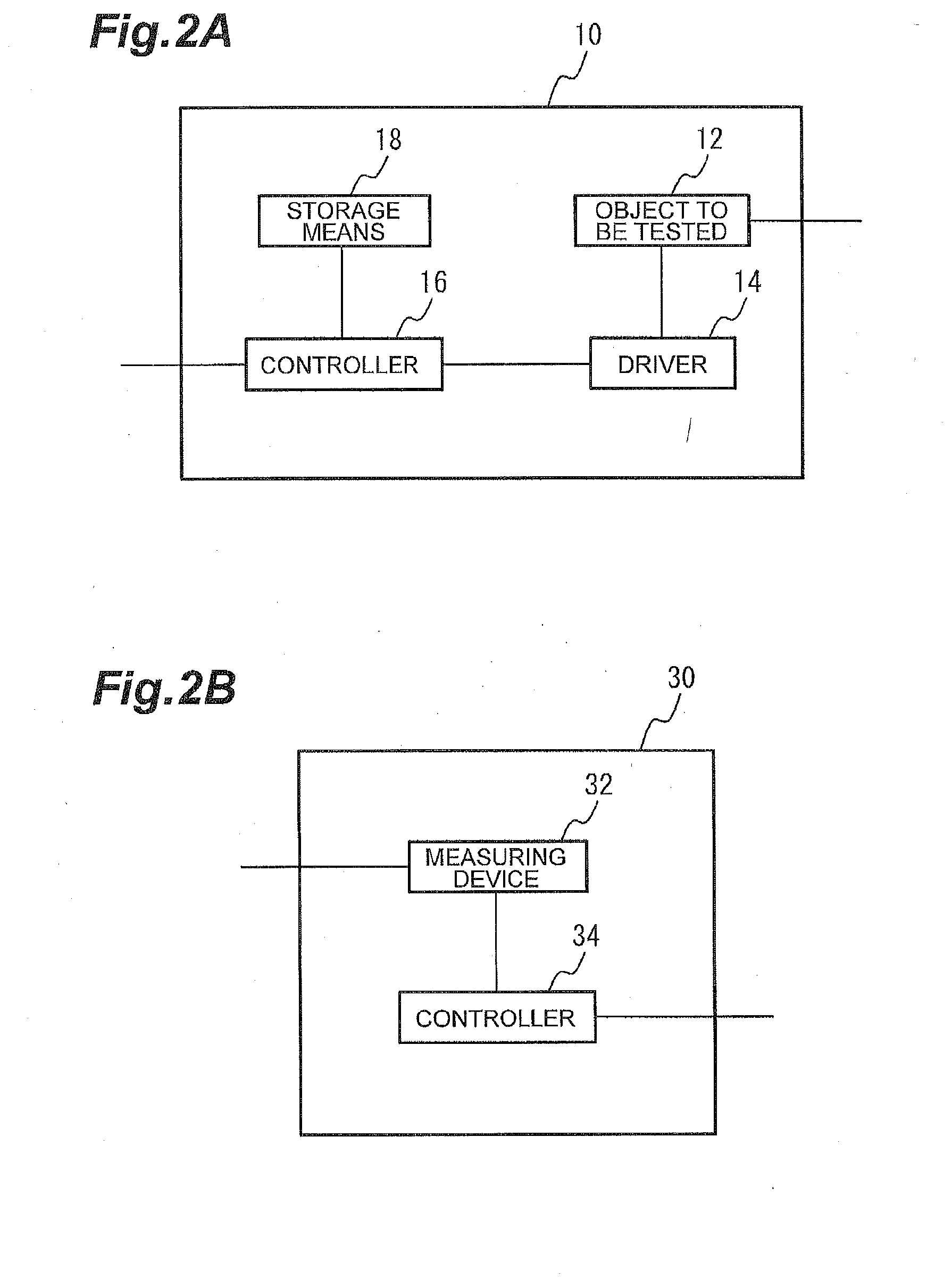
[0035]FIG. 2A is a block diagram illustrating details of the test target section 10, and FIG. 2B is a block diagram illus...
second embodiment
[0052]In a second embodiment, an example in which the temperature of the object to be tested 12 is changed to measure a change of the wavelength of the laser light output from the object to be tested 12 is shown. FIG. 5 is a block diagram illustrating an entire configuration of a test apparatus according to a second embodiment. As shown in FIG. 5, a test apparatus 200 according to the second embodiment further includes storage means 54. The storage means 54 is a hard disk drive, for example. The storage means 54 stores a table in which a connection order of test target sections 10a to be respectively connected to the plural measuring sections 30 is written. The controller 52 controls connection between the plural test target sections 10a and the plural measuring sections 30 according to the table. The other configuration of the second embodiment is the same as in the first embodiment shown in FIG. 1, and the description will not be repeated. Further, a control method of the test app...
third embodiment
[0060]In the first and second embodiments, an example in which the wavelength of the laser light output from the object to be tested 12 is measured by the measuring device 32 is shown, but in a third embodiment, a case in which a power penalty of an optical signal output from the object to be tested 12 is measured by the measuring device 32 will be described. FIG. 9 is a block diagram illustrating an entire configuration of a test apparatus according to the third embodiment. As shown in FIG. 9, a test apparatus 300 according to the third embodiment includes a switch section 60 and a controller 62, in addition to the plural test target sections 10, the plural measuring sections 30, the switch section 50, and the controller 52.
[0061]The switch section 60 is a matrix switch, for example. The controller 62 includes a CPU, a ROM, a RAM, and the like, and controls the switch section 60. The switch section 60 connects the plural test target sections 10 to light transmission lines L1 and L2...
PUM
 Abstract
Description
Claims
Application Information