High shooting speed dual-power gear structure of toy gun

a dual-power, toy gun technology, applied in the direction of compressed gas guns, white arms/cold weapons, weapons, etc., can solve the problems of repeated bullet loading, unstable period of ready-to-be-shot, and repeated bullet loading, so as to avoid repeated bullet loading, improve overall operating quality, and high shooting speed

Inactive Publication Date: 2015-03-05
INCORN HOBBY
View PDF10 Cites 16 Cited by
  • Summary
  • Abstract
  • Description
  • Claims
  • Application Information

AI Technical Summary

Benefits of technology

[0008]The primary objective of the invention is to provide a high shooting speed dual-power gear structure of toy gun that by having the second interlocking projecting pin for controlling the power supply of the electromotor and the first interlocking projecting pin be furnished on opposite sides of the compound gear, the action process and period between their contacting control can be enhanced to absorb the inertia rotation after the electromotor is powered off to effectively avoid the occurrence of repeated bullet loading and improve the overall operating quality.
[0009]The secondary objective of the invention is to provide a high shooting speed dual-power gear structure of toy gun that is applicable to the internal structure of most of the conventional toy gun to achieve the effect of operating quality and has the efficacy of being capable of lowering the developing and manufacturing cost.
[0010]To achieve the above-mentioned objective, the invention provides a high shooting speed dual-power gear structure of toy gun disclosed mainly includes a compound gear and an interlocking member. The compound gear has fine gear uniformly distributed on one side and at the circumference thereof, and coarse gear partially and uniformly distributed on the other side and at the circumference thereof with an indentation formed at the portion without gear teeth. The fine gear being driven by a electromotor through a transmission component is capable of driving a piston to compress a piston spring during the rotating process. A gun bolt core tube having an L-shaped hook part is furnished at the outer circumference of the piston. Moreover, a second interlocking projecting pin capable of controlling the power source of the electromotor is furnished on a side of the compound gear. The interlocking member being attached to a side opposite to the second interlocking projecting pin of the compound gear has a first interlocking projecting pin that contacts the L-shaped hook part to drive the gun bolt core tube into the action of bullet loading. By having the first interlocking projecting pin and the second interlocking projecting pin be furnished on opposite sides of the compound gear, the action process and period between their contacting control can be enhanced to absorb the inertia rotation after the electromotor is powered off to avoid the occurrence of repeated bullet loading.

Problems solved by technology

Another situation is that the side projecting pin preset on the compound gear hits the trigger and generate a reverse rotation and come off the preset position causing the electromotor unable to effectively mesh to drive resulting in either bullet-stuck or repeated bullet-loading such that two bullets are shot at a time.
However, in the actual action, in the course when the bullet is loaded, the gun bolt core tube and the piston are both in the compression process, thereby, the compression action of the piston will cause shaking of the gun bolt core tube that result in the bullet ready-to-be-shot persist an unstable period to wait for the piston to be completed the compression process before the shoot off action.
As a result, the other bullets can continue to drop causing the occurrence of repeated loading of the bullets.

Method used


Image

  • High shooting speed dual-power gear structure of toy gun
  • High shooting speed dual-power gear structure of toy gun
  • High shooting speed dual-power gear structure of toy gun

Examples


Embodiment Construction

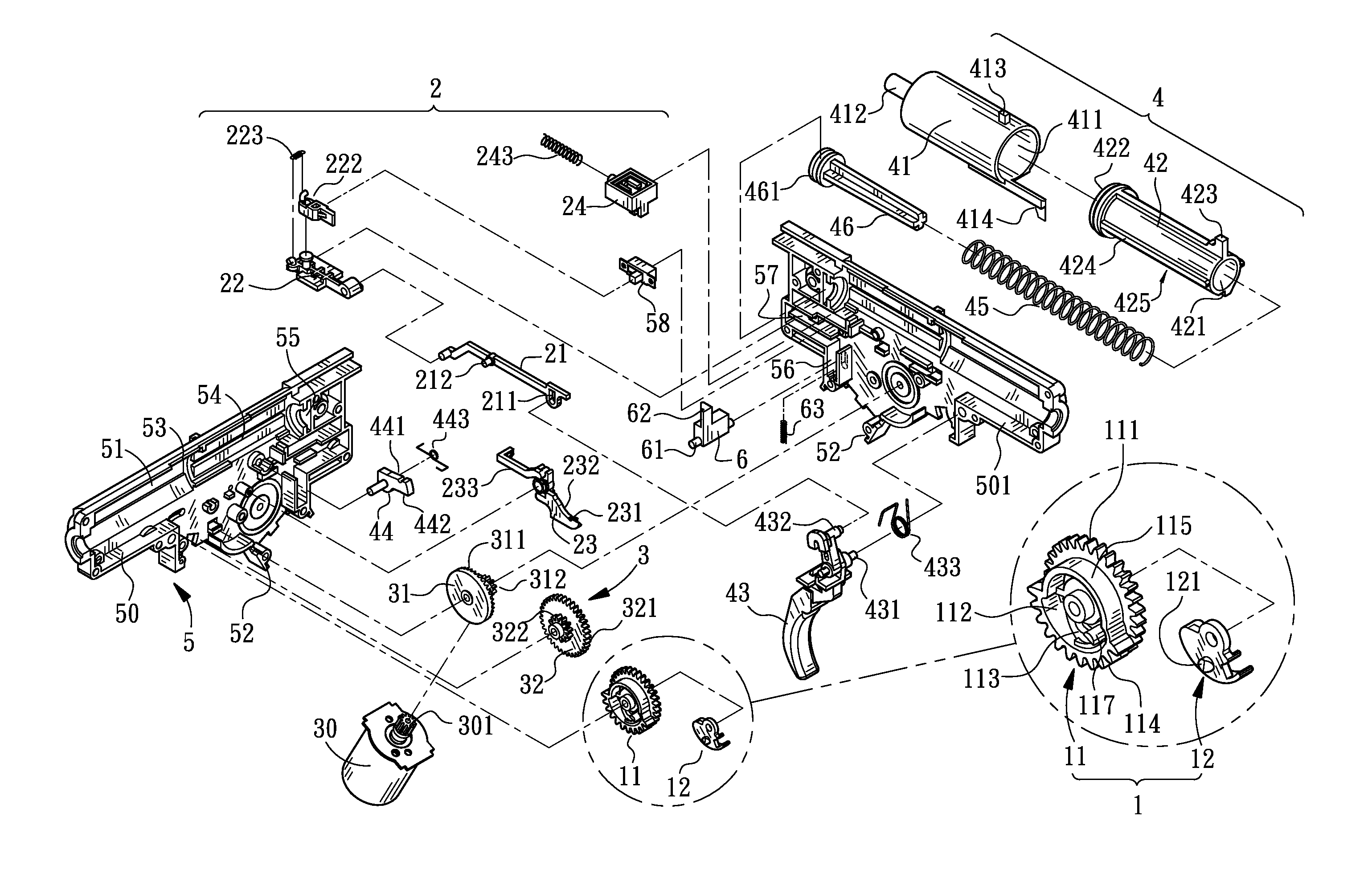
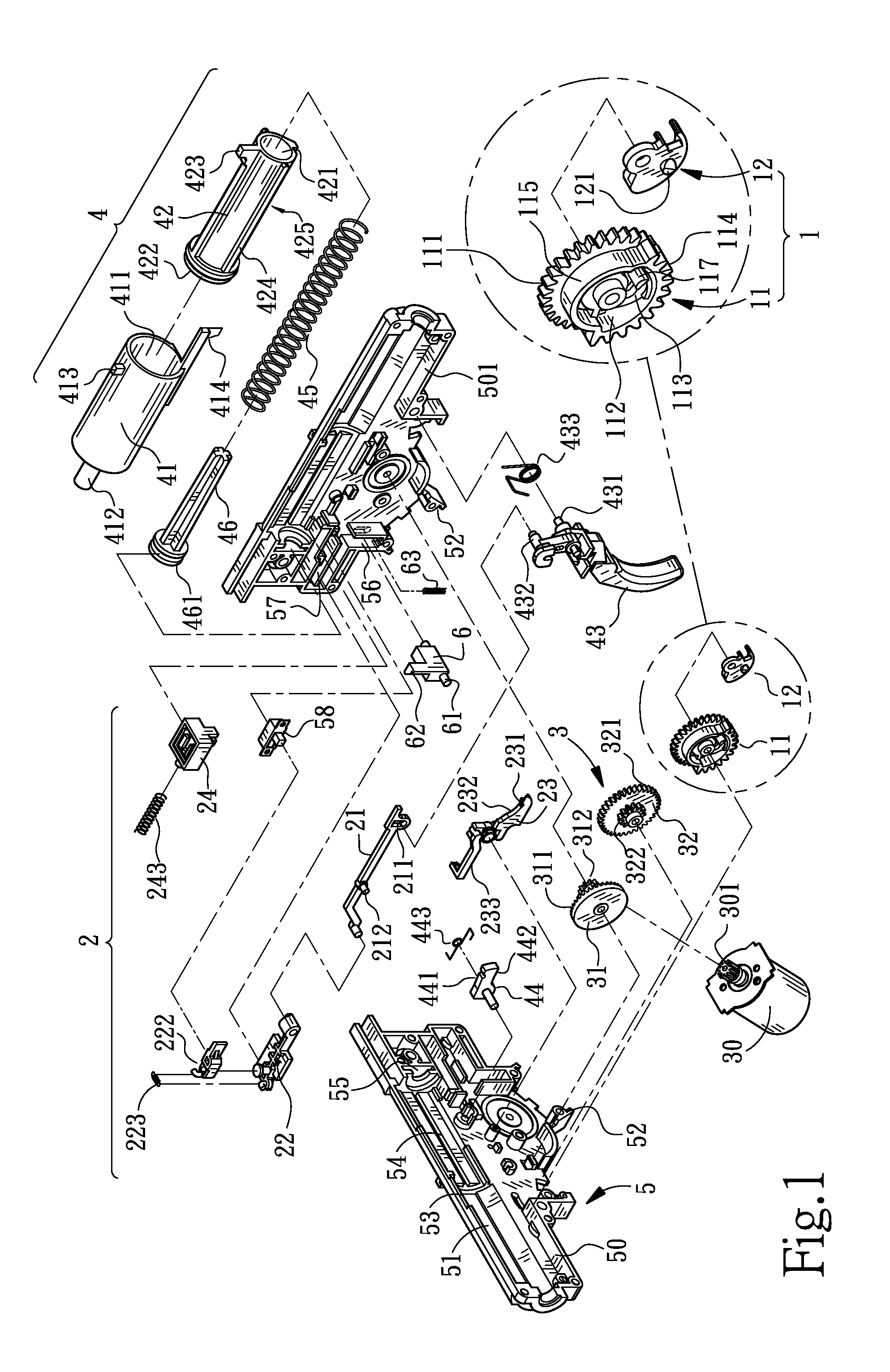
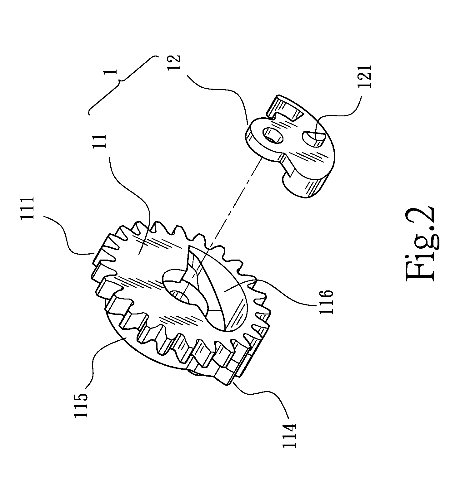
[0024]FIG. 1 is an isometric and exploded view of the high shooting speed dual-power gear structure of toy gun of the invention; FIG. 2 is an isometric view of the driving component the invention; FIG. 3 is an isometric and schematic view of a partial assembly of the invention; while FIG. 4 is a longitudinal cross-sectional view of the assembly of the invention. As shown in FIG. 1, FIG. 2, FIG. 3, and FIG. 4, the high shooting speed dual-power gear structure of toy gun of the invention mainly includes a driving component (1) and an interlocking component (2) wherein the driving components (1) are consisted of a compound gear (11) and an interlocking member (12). The compound gear (11) has fine gear (111) uniformly distributed on one side and at the circumference thereof, and coarse gear (114) partially and uniformly distributed on the other side and at the circumference thereof with an indentation (115) formed at the portion without gear teeth. Moreover, the compound gear (11) has a...


PUM


Abstract

A high shooting speed dual-power gear structure of toy gun disclosed mainly includes a compound gear and an interlocking member. The compound gear has fine gear uniformly distributed on one side and at the circumference thereof, and coarse gear partially and uniformly distributed on the other side and at the circumference thereof with an indentation formed at the portion without gear teeth. The fine gear being driven by a electromotor through a transmission component is capable of driving a piston to compress a piston spring during the rotating process. A gun bolt core tube having an L-shaped hook part is furnished at the outer circumference of the piston. Moreover, a second interlocking projecting pin capable of controlling the power source of the electromotor is furnished on a side of the compound gear. The interlocking member being attached to a side opposite to the second interlocking projecting pin of the compound gear has a first interlocking projecting pin that contacts the L-shaped hook part to drive the gun bolt core tube into the action of bullet loading. By having the first interlocking projecting pin and the second interlocking projecting pin be furnished on opposite sides of the compound gear, the action process and period between their contacting control can be enhanced to absorb the inertia rotation after the electromotor is powered off to avoid the occurrence of repeated bullet loading.

Description

FIELD OF THE INVENTION[0001]The invention relates to a high shooting speed dual-power gear structure of toy gun, and more particularly, to a high shooting speed dual-power gear structure of toy gun that is capable of effectively avoiding bullet loading repeatedly when it comes to triggering.DESCRIPTION OF THE PRIOR ART[0002]Among the current common toy gun products having projectile plastic bullet, there are pneumatic, and mechanical types of structure. The pneumatic type of toy gun makes use of an attached air bottle for providing the high-pressure gas to generate pressure propelled plastic (PP) bullets for projecting off the bullets. However, the mechanical type of toy gun makes use of the resilient spring force released from the compressed spring for propelling a piston to generate high-pressure gas for projecting off the bullets. Both types of toy gun have significant difference in structure since their power sources are different.[0003]In the “Control structure of dual-power ty...

Claims


Application Information

Patent Timeline
Patent Type & Authority Applications(United States)
IPC IPC(8): F41B11/646
CPCF41B11/646
Inventor YANG, CHUNG-KUAN
Owner INCORN HOBBY
Why Eureka
Try Eureka