Particle beam irradiation system and operating method

Active Publication Date: 2015-03-05
HITACHI LTD
View PDF1 Cites 14 Cited by
  • Summary
  • Abstract
  • Description
  • Claims
  • Application Information

AI Technical Summary

Benefits of technology

[0013]According to the present invention, beam irradiation at a desired irradiation energy stage can be performed in a short time, which shortens treatment time and improves the dose rate.
[0014]Also according to the present inventio

Problems solved by technology

The time required to perform the transition from extraction control at the extraction energy to deceleration control is one factor that lowers the dose rate and makes it difficult to shorten treatment time.
Likewise, direct transition from extraction control at the extraction energy to deceleration control cannot be performed when ion beam irradiation is interrupted due to a failure in the component devices making up the particle beam treatment system.
Where use is made of the operation control data that integrates into one range all energy ranges available for irradiation by the synchrotron and where irradia

Method used


Image

  • Particle beam irradiation system and operating method
  • Particle beam irradiation system and operating method
  • Particle beam irradiation system and operating method

Examples


Example

[0026]Some preferred embodiments of the present invention are explained below with reference to the accompanying drawings.

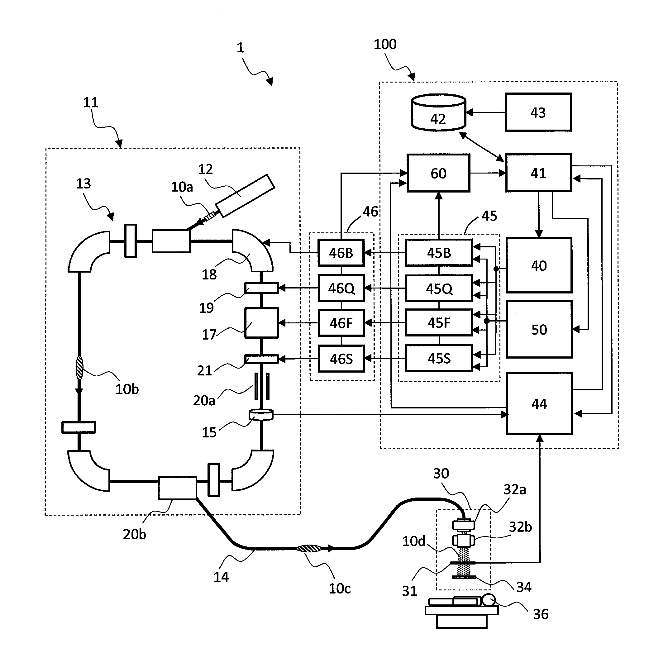
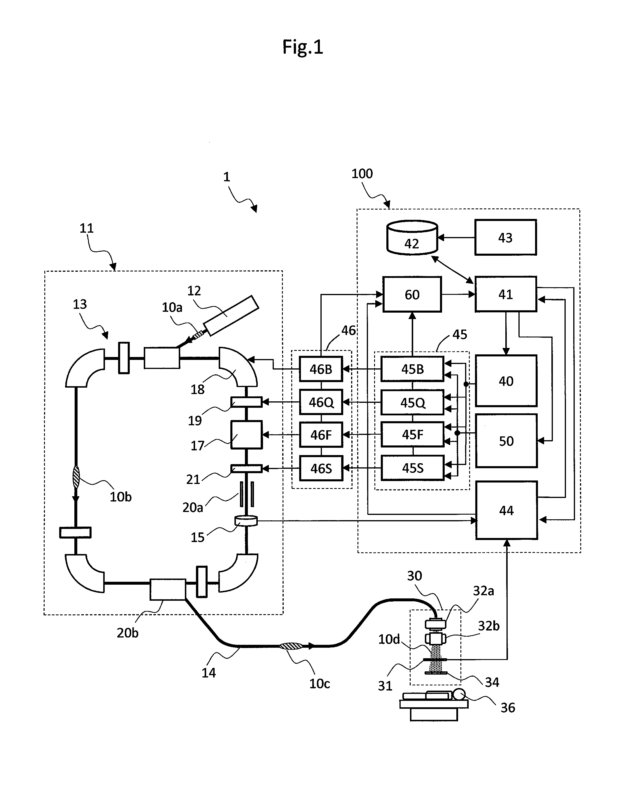
[0027]FIG. 1 is a diagram showing a configuration of a particle beam irradiation system as one preferred embodiment of the present invention.

[0028]As shown in FIG. 1, the particle beam irradiation system 1 of this embodiment includes an ion beam generator 11, a beam transport device 14, and an irradiation field forming apparatus (charged particle beam irradiation apparatus, simply called the irradiation apparatus hereunder) 30. The beam transport device 14 connects the ion beam generator 11 with the irradiation apparatus 30 installed inside a treatment room.

[0029]The ion beam generator 11 includes an ion source (not shown), a preaccelerator 12, and a synchrotron 13. The ion source is connected to the preaccelerator 12 that in turn is connected to the synchrotron 13. The preaccelerator 12 accelerates an ion beam 10 generated from the ion source up to an energy sta...


PUM


Abstract

The operation control data about the component device constituting the synchrotron 13 are structured to include an initial acceleration control data item, a plural extraction control data items, a plural energy change control data items that connect the plural extraction control data items. The plural extraction control data items include extraction condition setting data items and extraction condition cancellation data items corresponding to the plural extraction control data items. As a result, a particle beam irradiation system capable of controlling changes in beam energy, updating operation cycle, and extracting beam in a short time can be provided.

Description

BACKGROUND OF THE INVENTION[0001]The present invention relates to a particle beam irradiation system suitable for a particle beam treatment making use of a charged particle beam (ion beam) of protons or heavy ions. More particularly, the invention relates to a particle beam irradiation system capable of controlling changes in beam energy and providing operation cycle updates in a short time, and to an operating method for the system.[0002]The particle beam treatment is known as cancer radiotherapy whereby the affected part of a cancer patient is irradiated with an ion beam of protons or heavy ions for treatment. One method of ion beam irradiation is a scanning irradiation method such as one disclosed in “Review of Scientific Instruments,” Vol. 64, No. 8 (August 1993), pp. 2074-2093 (hereinafter, referred to as Non-patent Document 1).[0003]Where a synchrotron is adopted as an ion beam generator for controlling changes in beam energy as required of the scanning irradiation method as a...

Claims


Application Information

Patent Timeline
IPC IPC(8): A61N5/10B01J19/08
CPCA61N5/1077B01J19/081B01J2219/0801A61N2005/1092A61N2005/1087A61N5/1048
Inventor OGASAWARA, KOSUKENOMURA, TAKUYANISHIUCHI, HIDEAKI
Owner HITACHI LTD
Why Eureka
Try Eureka