Particle beam treatment apparatus and respiration navigation apparatus used therefor

Active Publication Date: 2010-08-19
MITSUBISHI ELECTRIC CORP
View PDF8 Cites 34 Cited by
  • Summary
  • Abstract
  • Description
  • Claims
  • Application Information

AI Technical Summary

Benefits of technology

[0011]When the patient consciously matches with the target respiration information, there arises a state in which the respiration is stable and is suitable for the operation cycle of the synchrotron, and hence oper

Problems solved by technology

Particularly, when the target diseased portion is a chest or an abdomen, a variation in the position or shape of the target diseased

Method used


Image

  • Particle beam treatment apparatus and respiration navigation apparatus used therefor
  • Particle beam treatment apparatus and respiration navigation apparatus used therefor
  • Particle beam treatment apparatus and respiration navigation apparatus used therefor

Examples


Embodiment Construction

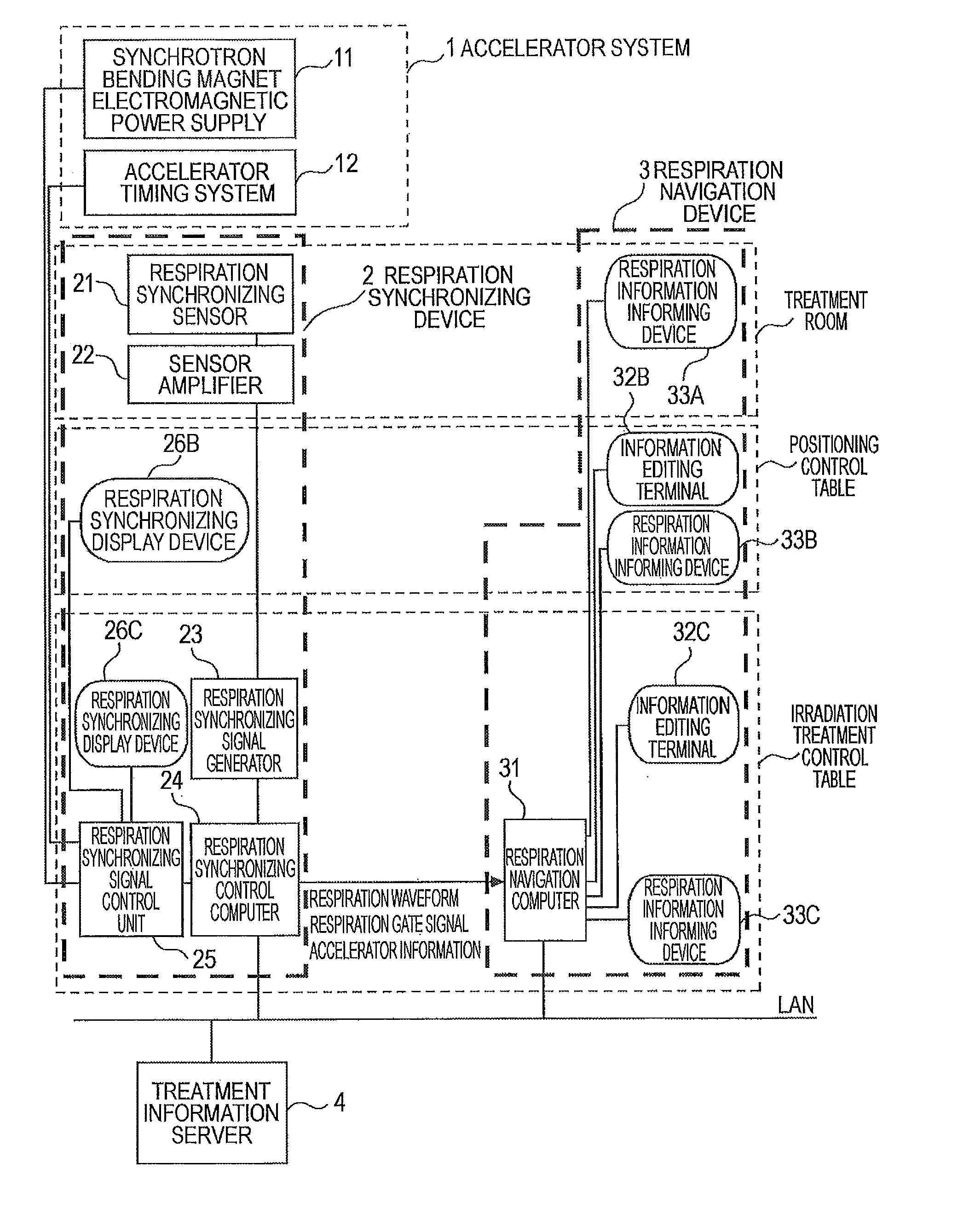
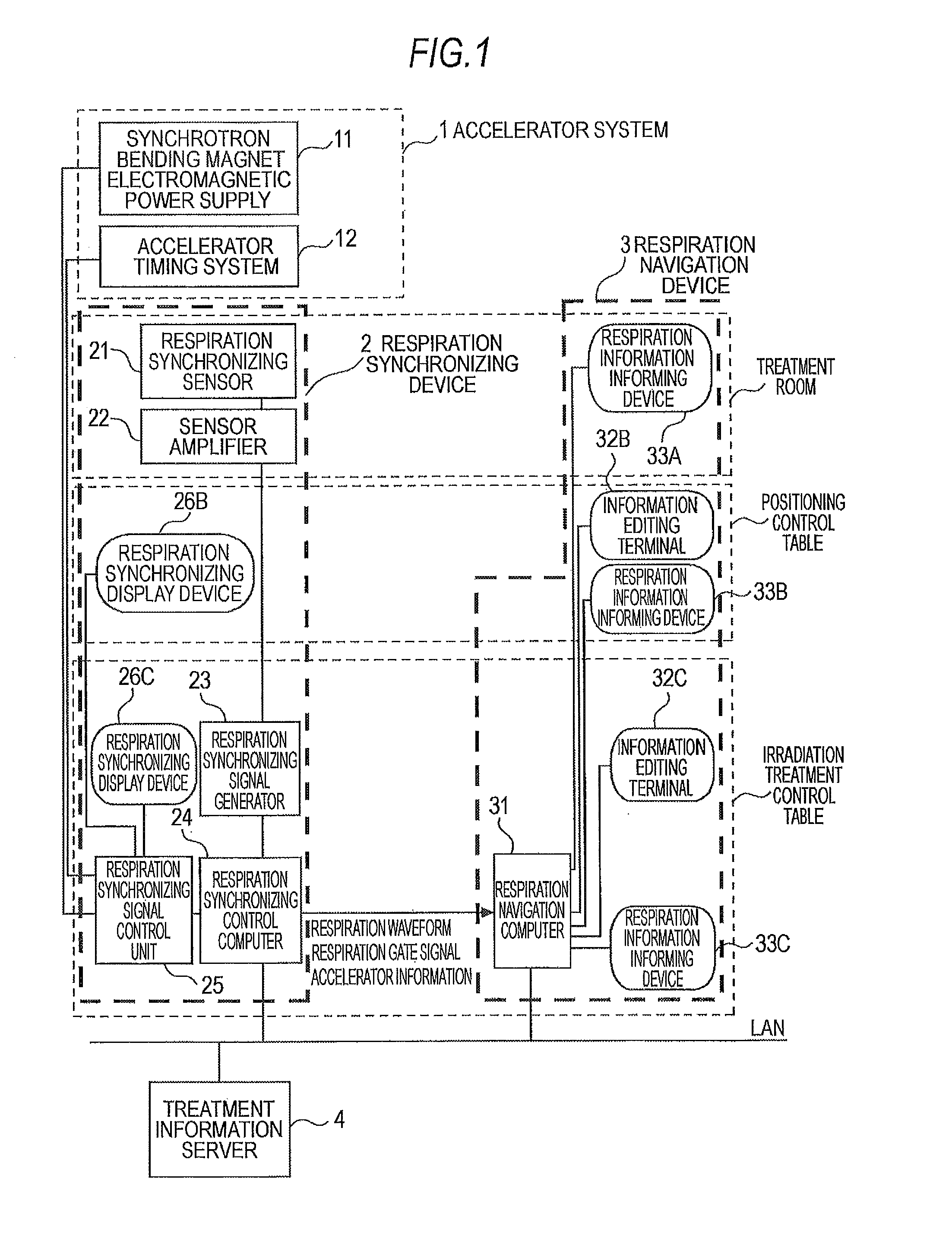
[0019]An embodiment of a particle beam treatment apparatus of the invention will be described by using a main configuration diagram of FIG. 1. FIG. 1 shows one room (for example, A) of plural treatment rooms, and shows an example in which three operation spaces are provided such as a treatment room, a positioning control table, and a irradiation treatment control table. A treatment operator performs an operation by using any one of three spaces. In the drawing, 1 denotes an accelerator system such as a synchrotron which accelerates a particle beam and includes a synchrotron bending magnet electromagnetic power supply 11 or an accelerator timing system 12. 2 denotes a respiration synchronizing device which is provided in the treatment room with a respiration synchronizing sensor 21 as a patient respiration measurement device which detects a respiration state of a patient and a sensor amplifier 22 for converting and amplifying a signal from the sensor 21, where the positioning control...


PUM


Abstract

Target respiration information is created in which a patient respiration pattern is set in advance to a cycle suitable for an operation cycle of a synchrotron, and the target respiration information is informed to the patient, so that a patient respiration timing becomes a state suitable for an operation of the synchrotron in such a manner that the patient consciously matches with the informed information.

Description

TECHNICAL FIELD[0001]The present invention relates to a particle beam treatment apparatus such as a particle beam cancer treatment apparatus.BACKGROUND ART[0002]For example, when a radiation treatment apparatus such as a cancer treatment apparatus is used, a countermeasure has been demanded for a case in which a position or a shape of a patient target diseased portion is changed due to a patient physiological phenomenon. Particularly, when the target diseased portion is a chest or an abdomen, a variation in the position or shape of the target diseased portion causes deterioration in treatment or diagnosis precision, and sometimes the patient may be necessarily exposed to radiation.[0003]In general, a particle beam treatment apparatus includes a particle beam generating unit such as a synchrotron, a particle beam irradiation unit which allows a patient to be irradiated with a particle beam generated from the particle beam generating unit through a particle beam transport system, a re...

Claims


Application Information

Patent Timeline
IPC IPC(8): A61N5/10A61B5/08
CPCA61N5/1049A61N2005/1087A61N5/1064A61N5/1068
Inventor HARADA, HISASHIHOSHI, AKIHIKO
Owner MITSUBISHI ELECTRIC CORP
Why Eureka
Try Eureka