
Electromagnetic interference (EMI) test apparatus

a technology of electromagnetic interference and test apparatus, which is applied in the direction of resistance/reactance/impedence, measurement devices, instruments, etc., can solve the problem that bci test may not be readily available for engineers when automotive products are sold

Inactive Publication Date: 2015-03-05
DELPHI TECH INC
View PDF8 Cites 8 Cited by
  • Summary
  • Abstract
  • Description
  • Claims
  • Application Information

AI Technical Summary

Benefits of technology

The patent is about a device that can be tested for its ability to resist interference from electromagnetic signals. It includes a special arrangement of layers and strips that work together to transmit RF energy from a generator to a load. The device also has a harness wire that connects to it. The patent describes a way to measure the performance of such arrangements and devices, which can be useful in improving their reliability and performance.

Problems solved by technology

Because of the expense of generating the high power RF signal, and the expense of providing a RF screen room for the BCI test, the BCI test may not be readily available for use by engineers when automotive products are being developed.

Method used


Image

  • Electromagnetic interference (EMI) test apparatus
  • Electromagnetic interference (EMI) test apparatus
  • Electromagnetic interference (EMI) test apparatus

Examples


Embodiment Construction

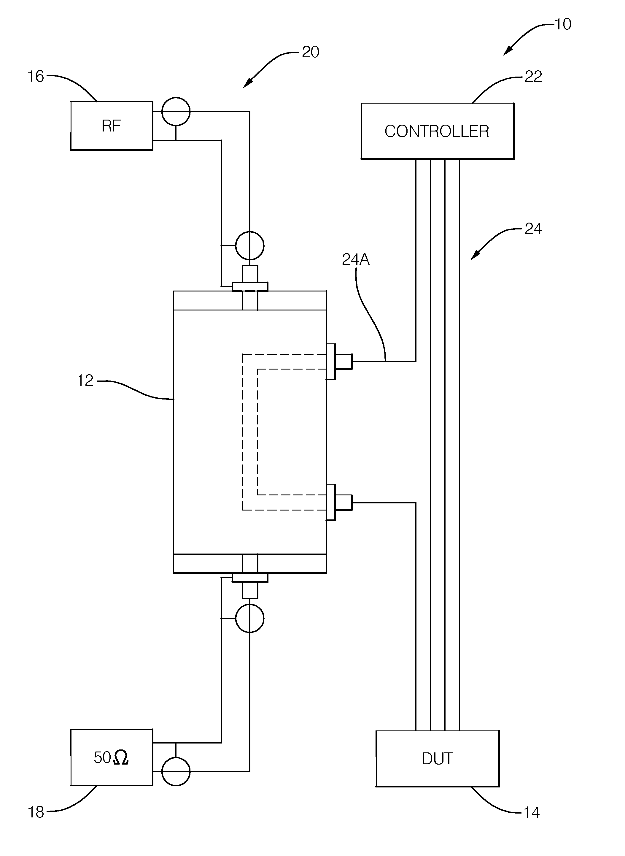
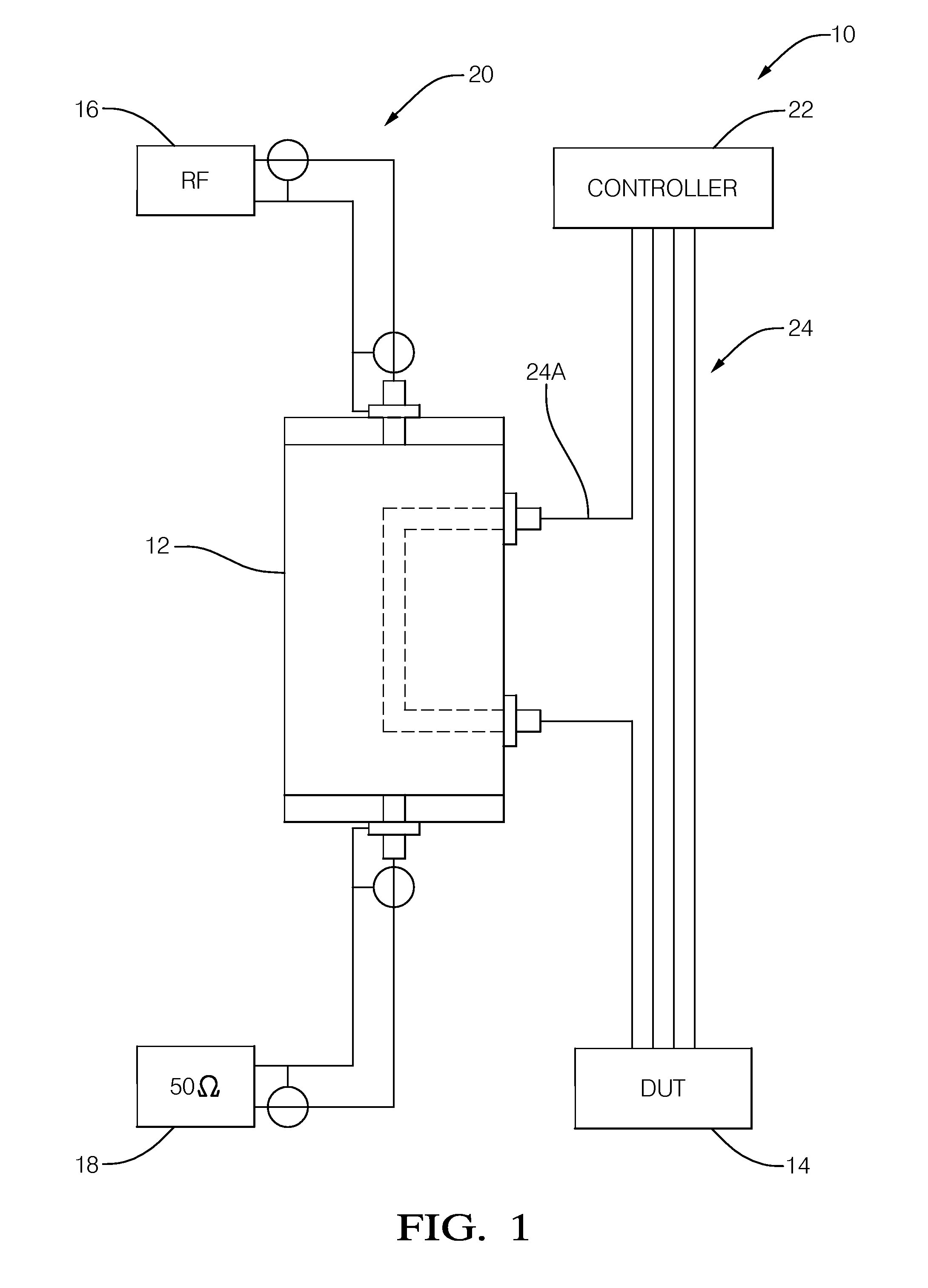
[0010]FIG. 1 illustrates a non-limiting example of a test system 10 that includes a radio-frequency (RF) energy coupling apparatus, hereafter referred to as the apparatus 12, for electromagnetic interference (EMI) susceptibility testing of a device 14. The device 14 is labeled in FIG. 1 as DUT to mean ‘device under test’. As described above, the known bulk current injection (BCI) test method is a relatively expensive test to perform as a high power radio frequency (RF) amplifier, a complicated current injection probe, and a RF screen room are needed to perform a BCI test. The test system 10 presented herein is a relatively low cost tool that can be used by engineers to, for example, pre-test the device 14 prior to submitting the device for BCI testing, or as an investigation tool when seeking to understand why the device 14 did not pass a BCI test. It is also recognized that the test system 10 may be used independent of BCI testing as part of a product development activity.

[0011]In ...


PUM


Abstract

A radio-frequency (RF) energy coupling apparatus for electromagnetic interference (EMI) susceptibility testing of a device. The apparatus includes a ground-plane, a micro-strip, a first dielectric layer, a coupling-strip, and a second dielectric layer. The micro-strip overlies the ground-plane. The first dielectric layer is interposed between the ground-plane and the micro-strip. The combination of the ground-plane, the micro-strip, and the first dielectric layer cooperate to form a micro-strip transmission line configured to propagate RF energy from a RF generator to a termination load. The coupling-strip overlies the micro-strip opposite the first dielectric layer. The coupling-strip is configured to couple RF energy from the micro-strip to a harness wire connected to the device. The second dielectric layer is interposed between the coupling-strip and the micro-strip.

Description

TECHNICAL FIELD OF INVENTION[0001]This disclosure generally relates to a radio-frequency (RF) energy coupling apparatus for electromagnetic interference (EMI) susceptibility testing of a device, and more particularly relates to using a micro-strip transmission line to couple RF energy into a wire connected to a device under test.BACKGROUND OF INVENTION[0002]Electrical devices sold to vehicle manufactures are typically required to comply with the Electromagnetic Interference (EMI) or Electromagnetic Compatibility (EMC) specifications established by the vehicle manufactures. One test used to determine compliance with the vehicle manufacture's specification is the so-called Bulk Current Injection (BCI) test. During BCI testing, bundles of wires are encompassed by a current injection probe that is clamped around the wires. A relatively high power (up to 50 Watts) radio frequency (RF) signal is supplied to the current injection probe to inductively couple RF currents into the wires encom...

Claims


Application Information

Patent Timeline
Patent Type & Authority Applications(United States)
IPC IPC(8): G01R31/00
CPCG01R31/002G01R31/001G01R31/006
Inventor S., VINEESHJOHNSON, BRIAN W.VIJAYARAJ, ASHOK KUMAR
Owner DELPHI TECH INC
Learn More