Cascaded switching power converter for coupling a photovoltaic energy source to power mains

a photovoltaic energy source and switching power converter technology, applied in the direction of circuit arrangement, ac-ac conversion, power conversion systems, etc., can solve the problems of system efficiency drop, system reliability deviation, system reliability impact,

Inactive Publication Date: 2011-02-10
CIRRUS LOGIC INC
View PDF20 Cites 44 Cited by
  • Summary
  • Abstract
  • Description
  • Claims
  • Application Information

AI Technical Summary

Benefits of technology

[0009]The converter includes a DC-DC converter that charges a link capacitor and an inverter that transfers power from the link capacitor to the mains supply. The DC-DC converter is controlled so that voltage ripple due to the AC current drawn by the inverter from the link capacitor does not affect the conditions at the input of the DC-DC converter. Therefore, the operating point of the PV source is maintained at a constant voltage / current operating point, generally at the MPP. The inverter and DC-DC converter can be controlled solely from the voltage across the link capacitor, and an integrated circuit providing such control provides an embodiment of the invention. The average voltage across the link capacitor can be controlled such that the energy stored in the link capacitor increases as the available power from the PV source rises, so that in response, the inverter will generate a larger current output onto the mains supply.

Problems solved by technology

If the ripple is not filtered, the variation in voltage at the output of the DC-DC converter causes large variations in the load current drawn from the PV energy source, which represent deviation from the MPP and therefore a drop in system efficiency.
Large electrolytic capacitors are undesirable both from a cost and volume standpoint, but in PV array applications, they are also undesirable for their impact on the reliability of the system.

Method used


Image

  • Cascaded switching power converter for coupling a photovoltaic energy source to power mains
  • Cascaded switching power converter for coupling a photovoltaic energy source to power mains
  • Cascaded switching power converter for coupling a photovoltaic energy source to power mains

Examples


Embodiment Construction

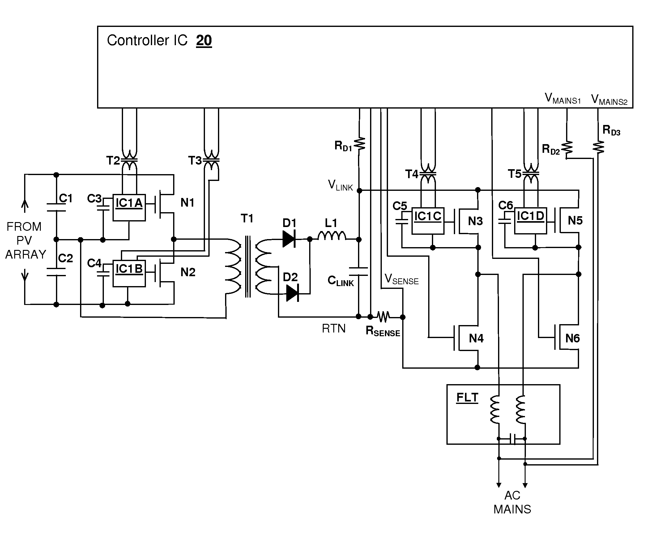
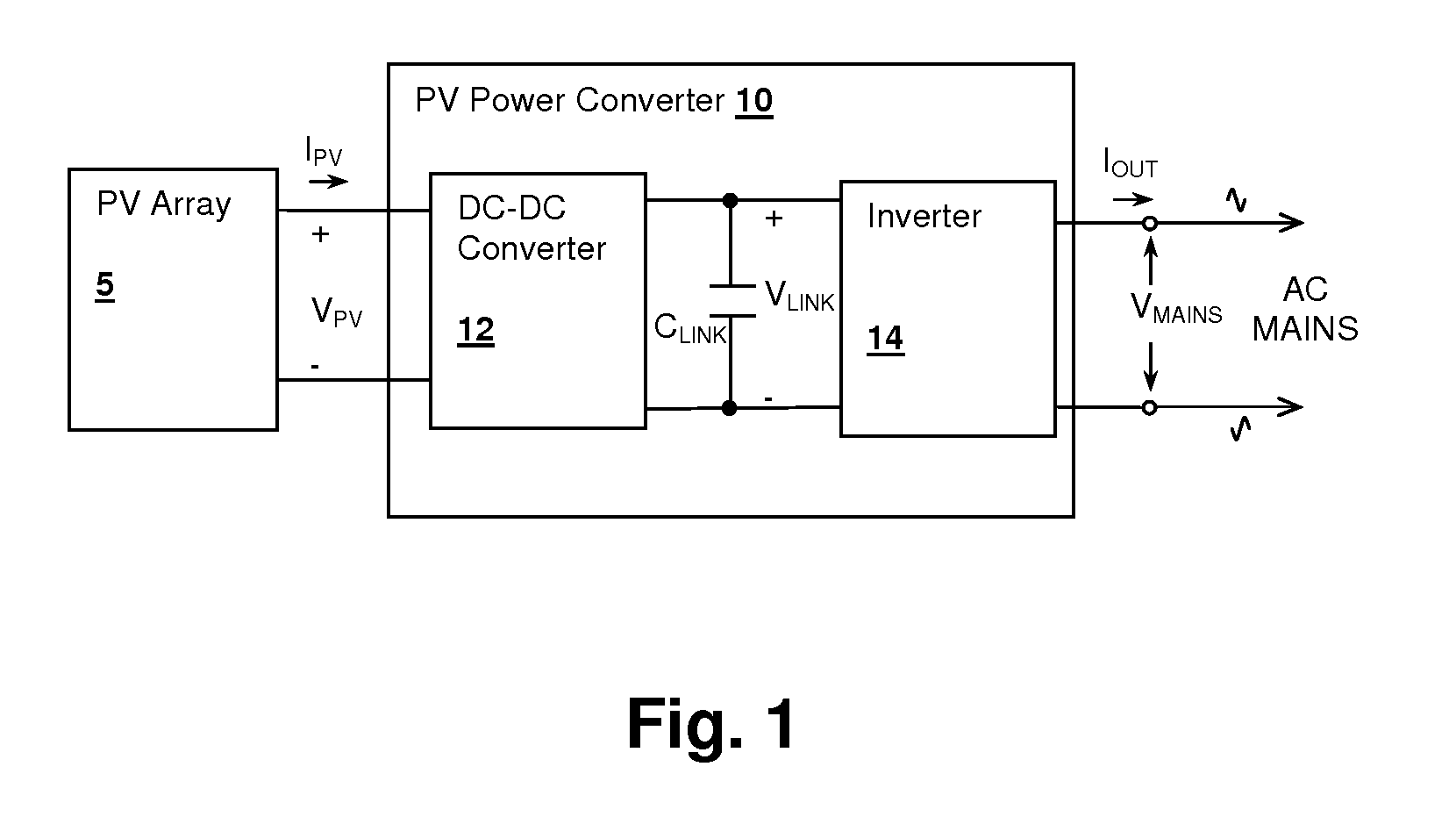
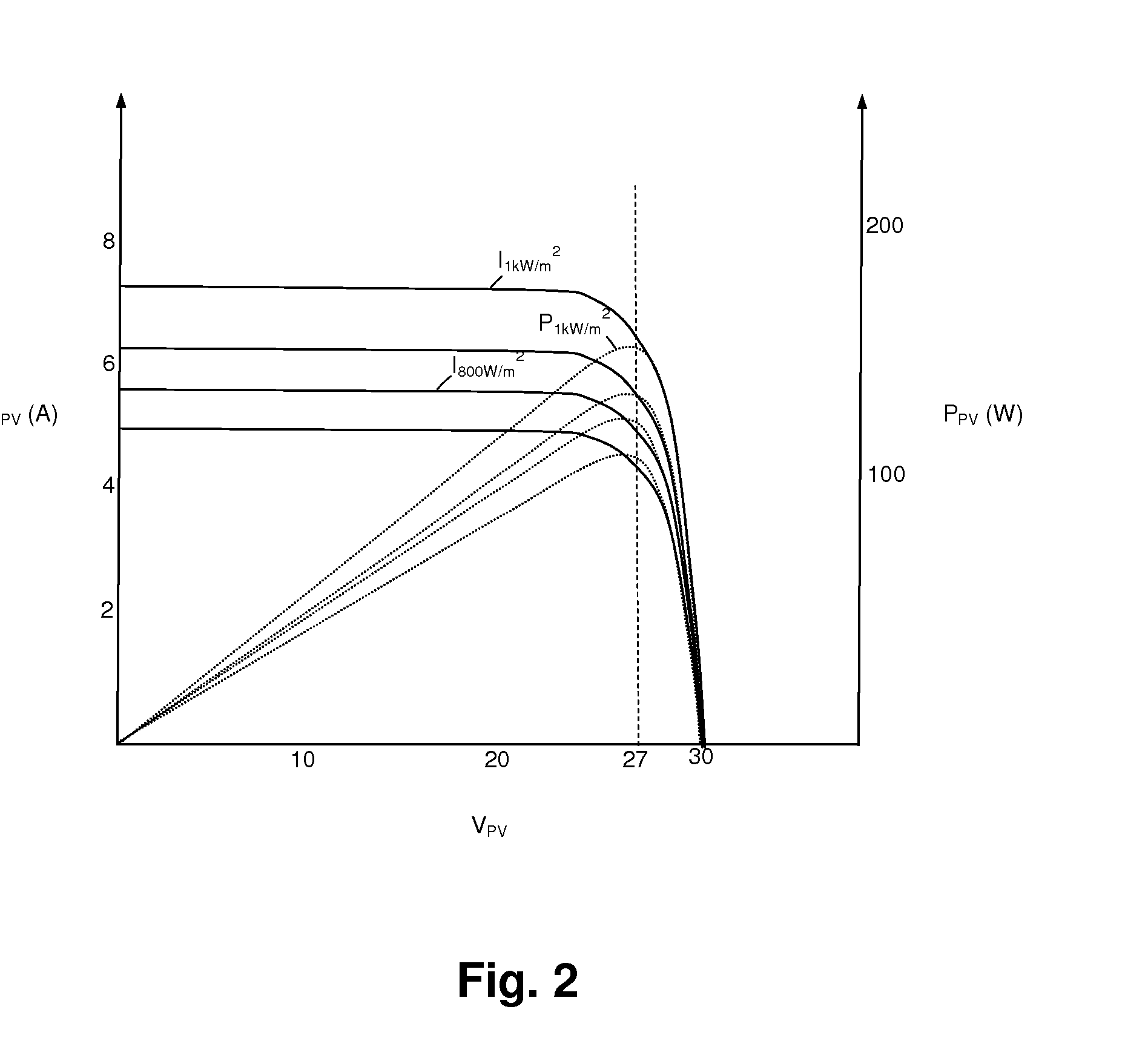
[0022]The present invention encompasses photovoltaic (PV) power converters, for coupling a PV power source to AC mains power lines. Energy is transferred to a link capacitor by a DC-DC converter, which provides the input source for an inverter that is synchronized to the AC mains. The control of the DC-DC converter is such that a low input impedance and a relatively high output impedance is maintained, so that as the AC input current of the inverter causes ripple on the link capacitor, the DC operating point of the PV power source is unaffected, and is maintained at a maximum power point (MPP) by action of the DC-DC converter control loop. The RMS value of the output current of the inverter is determined from the voltage across the link capacitor, which rises as the available current from the PV power source increases. The instantaneous output current of the inverter is controlled to be proportionate to and in-phase with the instantaneous mains voltage. The resulting system operatio...


PUM


Abstract

A cascaded switching power converter for coupling a photovoltaic (PV) energy source to power mains provides a high-efficiency and a potentially simple control mechanism for AC solar energy conversion systems. The PV energy source charges a capacitive storage element through a DC-DC converter, and an inverter couples energy from the capacitive storage element to the mains supply. The DC-DC converter is controlled so that ripple present on the capacitive storage element due to current drawn by the inverter is not reflected at the input of the DC-DC converter, which is accomplished by varying the conversion ratio of the DC-DC converter with the ripple voltage present across the capacitor. The average voltage of the capacitor can also be increased with increases in the available power output from the PV energy source, so that a corresponding increase in power is transferred to the mains supply.

Description

[0001]The present Application is a National Stage Application filed under 35 U.S.C. §371 of PCT Application US09 / 2009 / 041910 filed on April 28, 2009 by the same inventor, and which claims priority to U.S. Provisional Patent Application 61 / 048,805 filed on Apr. 29, 2008.FIELD OF THE INVENTION[0002]The present invention relates generally to switching power inverter circuits, and more specifically, to a cascaded switching power converter for coupling a photovoltaic energy source to power mains.BACKGROUND OF THE INVENTION[0003]Photovoltaic (PV) solar energy production has been of interest for several decades, and with consistent decreases in the cost of solar arrays, along with a growing cost of non-solar energy, the penetration of PV energy sources is expected to continue to rise. Interest in PV and other systems in reducing greenhouse gas emissions and improving air quality can also be expected to raise the demand for PV energy sources.[0004]In order to use PV energy sources in conjun...

Claims


Application Information

Patent Timeline
Patent Type & Authority Applications(United States)
IPC IPC(8): H02M5/45
CPCH02M1/14H02M7/4807H02J3/383Y02E10/563H02M7/53832H02J2300/24H02J3/381Y02E10/56H02J3/40
Inventor MELANSON, JOHN L.
Owner CIRRUS LOGIC INC
Why Eureka
Try Eureka