Tri-mode co-boresighted seeker

a sensor system and co-boresighted technology, applied in direction controllers, antenna details, antennas, etc., can solve the problems of restricting the collection aperture, limiting the amount of laser energy, and exhibiting typical degraded performan

Active Publication Date: 2005-05-05
NORTHROP GRUMMAN SYST CORP
View PDF10 Cites 43 Cited by
  • Summary
  • Abstract
  • Description
  • Claims
  • Application Information

AI Technical Summary

Benefits of technology

[0013] It is still yet another object of the invention to provide a tri-mode seeker providing extraction and diversion of optical signals from a joint or common RF optical signal path while causing substantially no disturbance to the RF signal as it propagates in the signal path.
[0014] It is still yet another object of the invention to provide a tri-mode co-boresighted seeker that permits all three signal modes to utilize the full primary mirror aperture while providing two beam splitting actions so that all three signals are collected in different locations with minimal interference with or impact on each other.

Problems solved by technology

Single mode sensors used, for example, in missile seekers are well known in the state of the art but typically exhibit degraded performance because of false target acquisitions.
In such a configuration, the reception of laser energy is restricted to a relatively small zone on the outer periphery of the primary mirror, thus restricting the collecting aperture since it severely limits the amount of laser energy which can be detected.
Also, the packaging is awkward and crowded, severely reducing the overall packaging efficiency.
Additionally, propagating a laser wavelength to the IR focal plane has also been attempted, but it degrades IR performance due to the limited selection of materials that pass all desired wavelengths and their color properties which make it impossible to fully color correct the optical design, particularly over the IR band.
The constraints on material selections also raise an issue of electromagnetic interference (EMI) susceptibility in the IR detector apparatus.
These include distortion of the IR wave front and loss of image quality and a lack of volume for packaging the necessary support electronics.
This location makes coating design very difficult, if not impossible, by demanding the coating also pass the IR band while imposing a wide range of incident angles that it must accommodate.
Thus, all prior approaches have inherent limitations which impose some form of penalty and / or difficulty in a suitable overall system design.

Method used


Image

  • Tri-mode co-boresighted seeker
  • Tri-mode co-boresighted seeker
  • Tri-mode co-boresighted seeker

Examples


Embodiment Construction

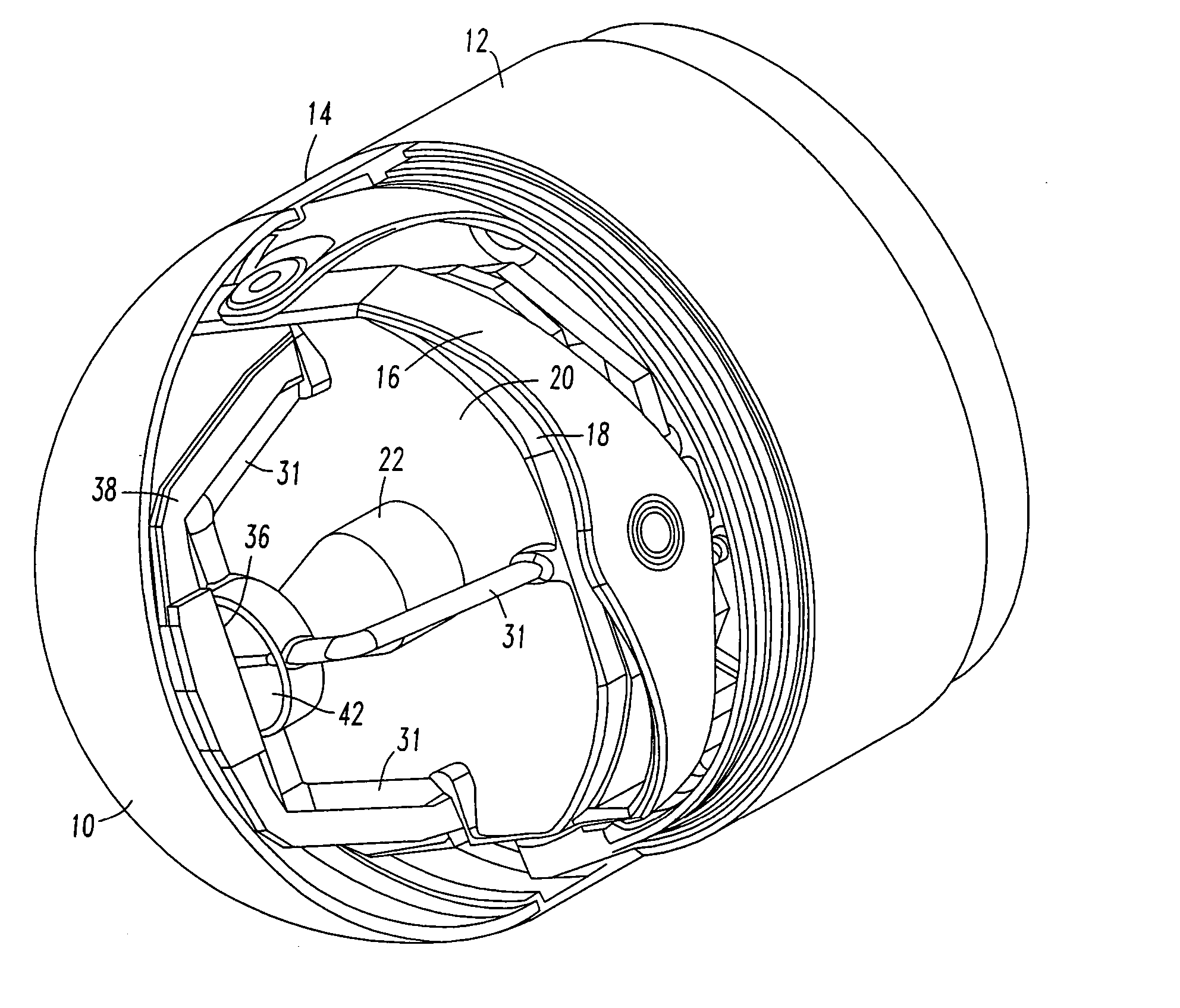
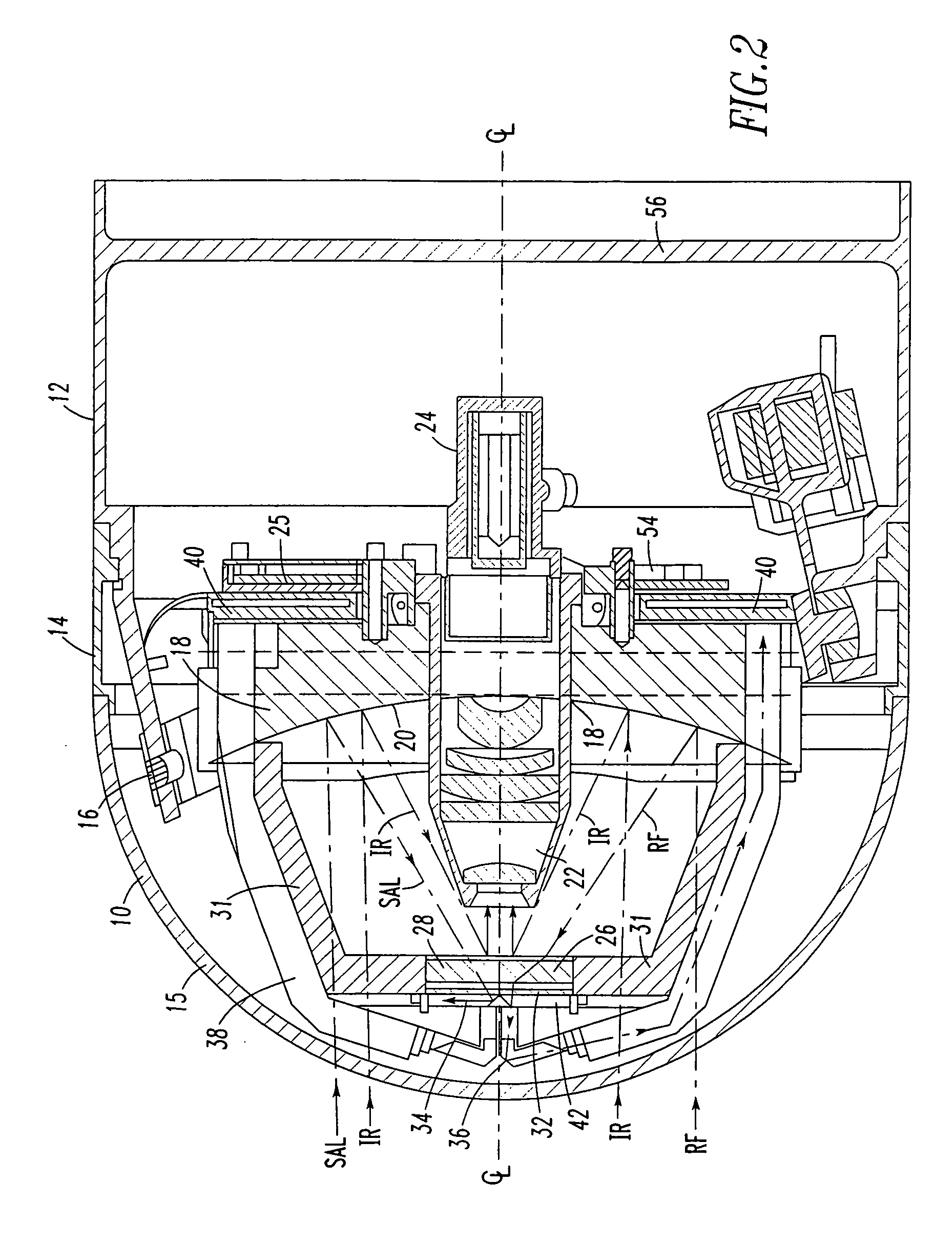
[0030] This invention is directed to a common aperture for three sensors of millimeter wave (MMW), infrared (IR) and semi-active laser (SAL) energy which are aligned on a common boresight or central longitudinal axis (CL) of seeker apparatus used, for example, in an airborne platform such as a missile and which allows all three modes to simultaneously use the full transmitting / receiving aperture.

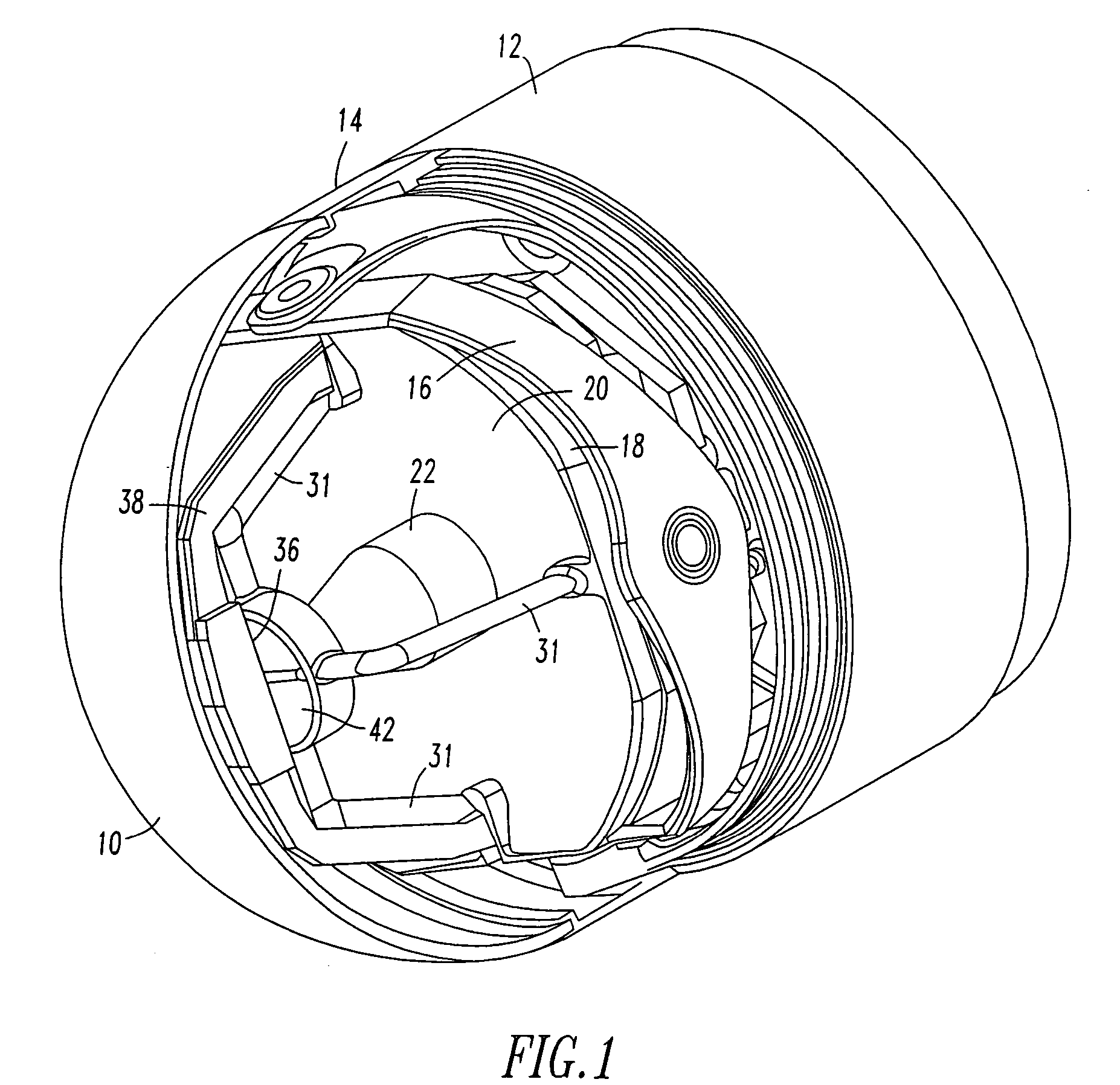
[0031] Referring now to the drawings wherein like reference numerals refer to like components throughout, reference is first made to FIGS. 1-9 which disclose the details of a first embodiment of the invention. Reference numeral 10 denotes the radome of a tri-mode seeker assembly including an annular base member 14 to which is secured a housing 12 for supporting a gimbal assembly 16 as well as attachment of the radome 10. A primary mirror assembly 18 including a parabolic reflecting surface 20 is mounted on the gimbal assembly 16 so that it can be controlled to move independently in two orth...


PUM


Abstract

A tri-mode co-boresighted seeker including a primary collecting mirror assembly having a parabolic surface and a forwardly located dielectric secondary mirror assembly including a dielectric mirror coating which reflects infrared (IR) energy to an IR detector assembly located on a central longitudinal axis on one side of the secondary mirror while providing substantially unobstructed propagation of millimeter wave RF energy and laser energy in a joint or common signal path therethrough to means located on the other side of the secondary mirror for extracting and diverting laser energy away from the common RF-optical signal path to a laser sensor assembly while causing little or no disturbance to the RF signal as it propagates to a co-located bifurcated waveguide assembly which couples the RF energy to an RF sensor means located behind the primary mirror.

Description

BACKGROUND OF THE INVENTION [0001] 1. Field of the Invention [0002] This invention relates generally to a multi-mode sensor system located in a common transmitting / receiving aperture and, more particularly, to a tri-mode, co-boresighted sensor system located on an airborne platform, such as a missile seeker. [0003] 2. Description of Related Art [0004] Single mode sensors used, for example, in missile seekers are well known in the state of the art but typically exhibit degraded performance because of false target acquisitions. In order to overcome this inherent deficiency, a dual-mode seeker including millimeter wave (MMW) and infrared (IR) sensors in a common aperture have been developed. One such system is shown and described in U.S. Pat. No. 5,214,438, entitled “Millimeter Wave and Infrared Sensor in a Common Receiving Aperture”, issued to T. C. Brusgard et al. on May 25, 1993. More recently, a tri-mode seeker additionally including a laser spot tracker has been developed by the a...

Claims


Application Information

Patent Timeline
Patent Type & Authority Applications(United States)
IPC IPC(8): F41G7/00F41G7/22
CPCF41G7/008F41G7/2213F41G7/2246F41G7/2293F41G7/226F41G7/2286F41G7/2253F41G7/22F41G7/00F41G7/20
Inventor KIERNAN, SHERWOOD C. JR.WALKER, DONALD J.STAMM, DANIEL E.YABLON, WILLIAM B.DISHOP, PAUL M.
Owner NORTHROP GRUMMAN SYST CORP
Why Eureka
Try Eureka