Energy efficient bi-stable permanent magnet actuation system

a permanent magnet actuation system, bi-stable technology, applied in the direction of magnetic bodies, electrical equipment, electrical circuit arrangements, etc., can solve the problems of increasing the difficulty of energy saving applications, requiring the switching means in the h-bridge to be quite power intensive, and using fixed voltage power sources

Active Publication Date: 2015-03-05
ROBERTSON GLEN A
View PDF9 Cites 16 Cited by
  • Summary
  • Abstract
  • Description
  • Claims
  • Application Information

AI Technical Summary

Benefits of technology

[0011]A bi-stable permanent magnet actuator system (BSPMAS) that is more adaptable to energy saving applications includes control electronics comprising: a power source that can be of any power level to include low voltage batteries and solar cells with low average watts (energy per time), a voltage conditioner such as a DC / DC converter, an energy storage device such as a capacitor, an output circuit such as an H-Bridge switching circuit, and a control circuit for controlling delivery of current pulses from the energy storage device through the output circuit to the control coil, and can include segmented, parallel connected control coil to reduce the input voltage from the power source.

Problems solved by technology

Thus requiring the switching means in the H-bridge to be quite power intensive.
Using fixed voltage power sources makes versatility to energy saving application, like solar power, much harder, especially when high voltages or high currents are needed.
Still further, as a bi-stable permanent magnet actuator increases in size the control coil increase proportionally, which increases their resistance, which increases the voltage required to get the proper current through the control coil, which increases the size of the power source.

Method used


Image

  • Energy efficient bi-stable permanent magnet actuation system
  • Energy efficient bi-stable permanent magnet actuation system
  • Energy efficient bi-stable permanent magnet actuation system

Examples


Embodiment Construction

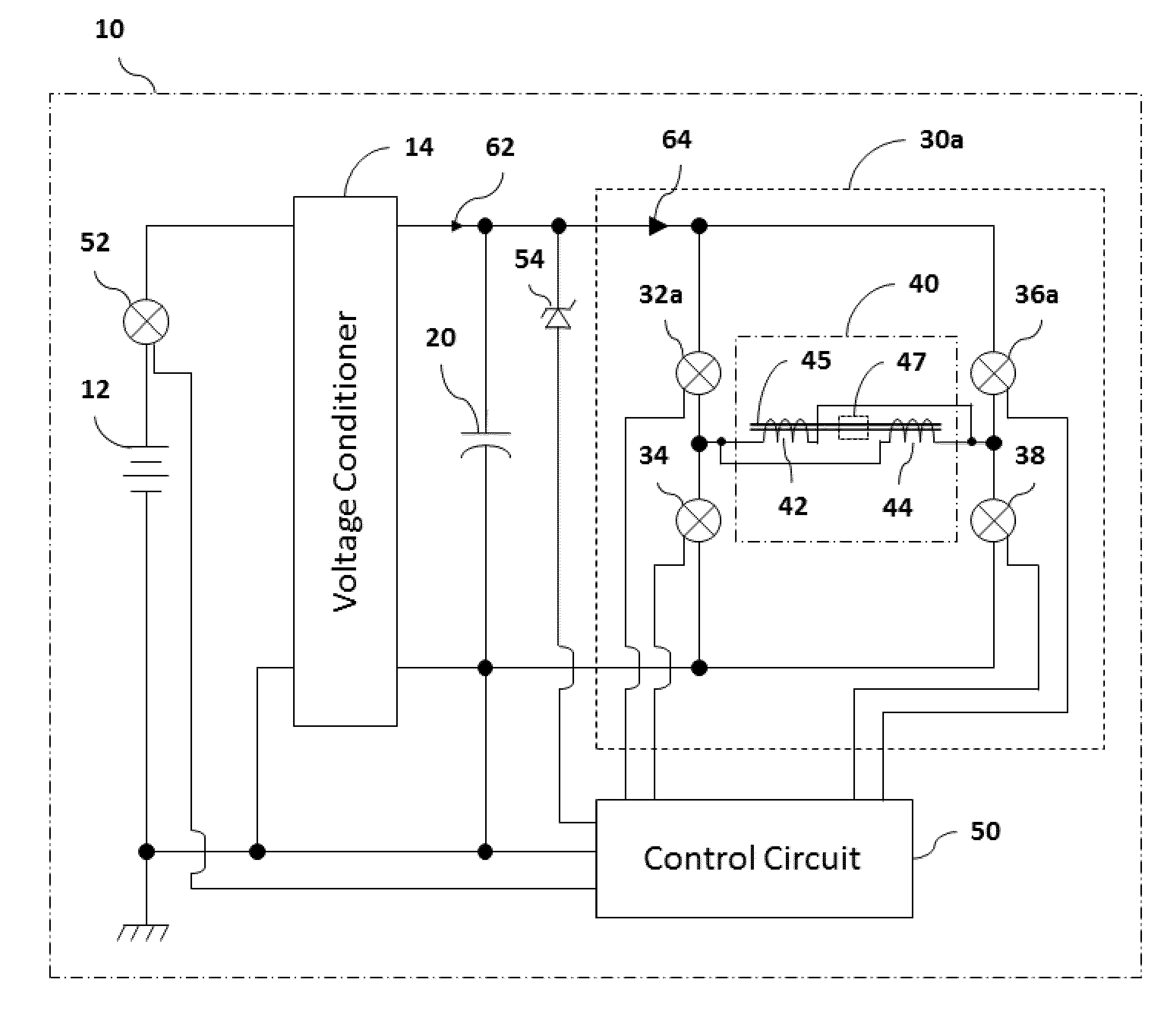
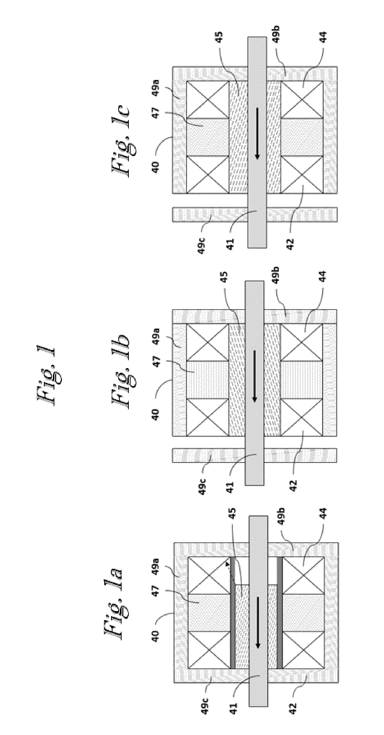
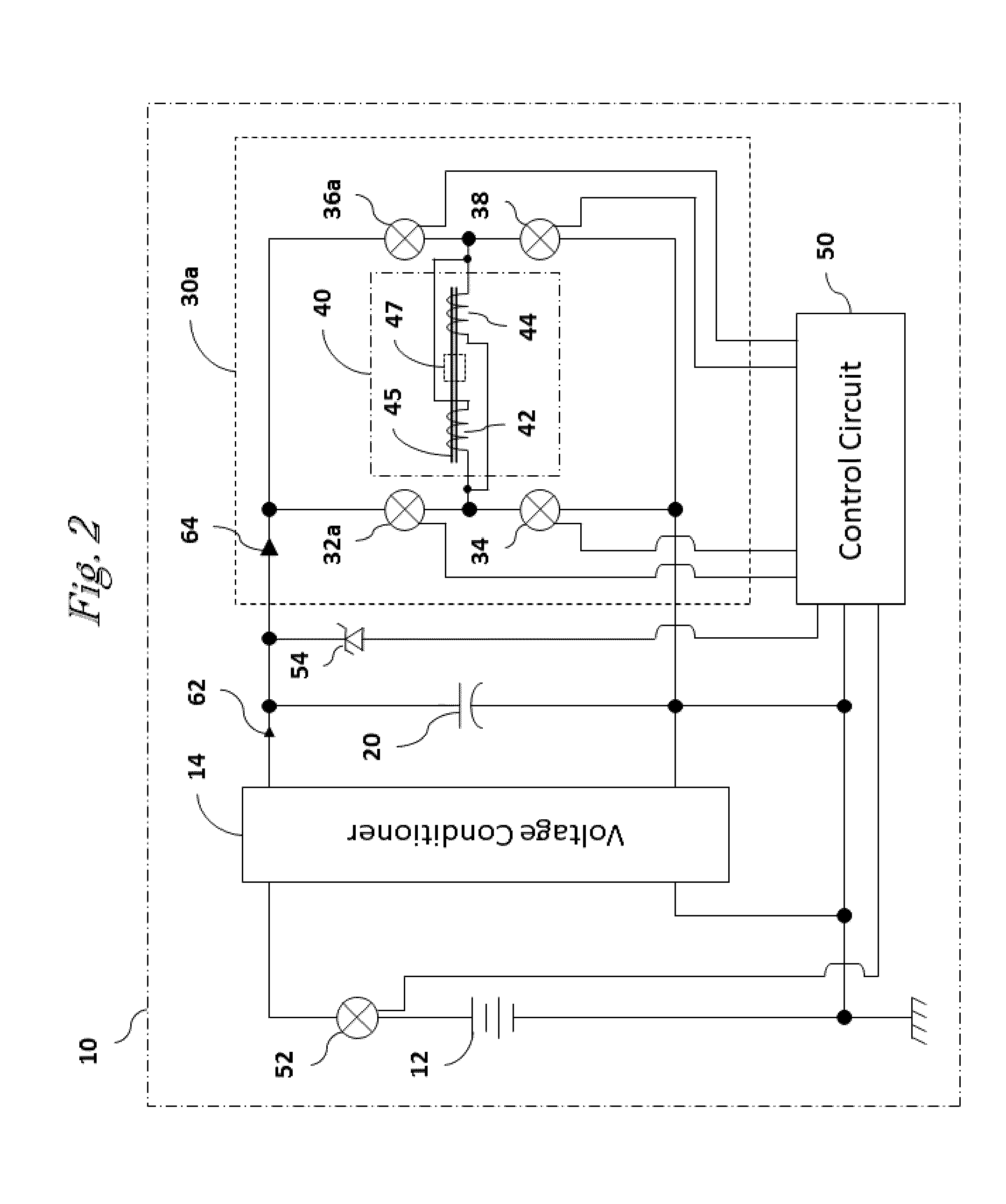
[0017]Referring to FIG. 1, a bi-stable permanent magnet actuator 40 can be produce in several forms, as shown, an outer magnetic body 49 incases control coil 42, 44 about a center pole piece 45, one on either side of a permanent magnet 47. The outer housing 49 is broken into three parts: a fixed outer part 49a and pole ends 49b, 49c that may be moveable or fixed. A shaft 41 is shown that is used to convey the movement and force from the bi-stable permanent magnet actuator 40. It is understood that bi-stable permanent magnet actuators 40 can be produced with only one coil 42 or 44.

[0018]The control coil 42, 44 form a single current directional path in one of two directions to produce a single directional path magnetic field in one of two directions to divert the permanent magnet's 47 magnetic field in one of two directions from the poles of the permanent magnet 47, wherein:

[0019]FIG. 1a, to bi-directionally attract the moveable central pole piece 45 to fixed pole end 49b or 49c as do...


PUM

PropertyMeasurementUnit
timeaaaaaaaaaa
fusing currentaaaaaaaaaa
timeaaaaaaaaaa

Abstract

Bi-stable permanent magnet actuation is a technique employed to move and magnetically hold an armature in electromechanical devices including some valves, wherein, permanent magnets are employed in a manner that places their magnetic field in a bi-stable state to allow a control coil to divert the permanent magnet's magnetic field in one of two directions within the surrounding magnetic material. Control is established using an actuation system comprising, a power source to deliver the desired level of energy, a voltage conditioner such as a DC/DC converter matched to the power source and electromechanical device, an energy storage device such as a capacitor, an output circuit such as an H-Bridge switching circuit, and a control circuit for controlling delivery of short duration current pulses from the energy storage device through the output circuit to the electromechanical device's control coil. Thus, an energy efficient bi-stable permanent magnet actuation system is produced.

Description

RELATED APPLICATIONS[0001]The present application may find use in systems such as is disclosed in the U.S. Patent application entitled “COMPACT ELECTROMECHANICAL MECHANISM AND DEVICES INCORPORATING THE SAME,” having pub. No. 20120175974A1, pub. date Jul. 12, 2012, pending; U.S. Patent application entitled “DIVERGENT FLUX PATH MAGNETIC ACTUATOR AND DEVICES INCORPORATING THE SAME,” having Ser. No. 13 / 489,638, filed Jun. 6, 2012, pending; U.S. Patent application entitled “DIVERGENT FLUX PATH MAGNETIC ACTUATOR AND DEVICES INCORPORATING THE SAME,” having Ser. No. 13 / 489,682, filed Jun. 6, 2012, pending; U.S. Patent entitled “PERMANENT MAGNET LATCHING SOLENOID,” having U.S. Pat. No. 6,265,956 B1, date Jul. 24, 2001; J.P. patent, “SOLENOID ACTUATOR,” having U.S. Pat. No. 7,037,461, date 1995, U.S. Patent entitled “LATCHING SOLENOID WITH MANUAL OVERRIDE,” having U.S. Pat. No. 5,365,210, date Nov. 15, 1994; U.S. Patent entitled “ELECTROMAGNETIC DEVICE,” having U.S. Pat. No. 3,381,181, date A...

Claims


Application Information

Patent Timeline
Patent Type & Authority Applications(United States)
IPC IPC(8): H01F7/06
CPCH01F7/064H01F7/1615H01F2007/1669
Inventor ROBERTSON, GLEN A.
Owner ROBERTSON GLEN A
Why Eureka
Try Eureka