Light-emitting unit, light-emitting device, illumination device, and vehicle headlight

a technology of illumination device and light-emitting unit, which is applied in the direction of semiconductor devices for light sources, fixed installations, lighting and heating apparatus, etc., can solve the problems of inefficient use of fluorescence and decrease and achieve the effect of improving the efficiency of light us

Active Publication Date: 2015-03-05
SHARP FUKUYAMA LASER CO LTD
View PDF10 Cites 60 Cited by
  • Summary
  • Abstract
  • Description
  • Claims
  • Application Information

AI Technical Summary

Benefits of technology

[0020]According to one aspect of the present invention, the present invention yields the effect of providing a light-emitting unit having improved efficiency of light use.

Problems solved by technology

Unfortunately, the illumination device 300, which is configured such that the excitation light source 301 and the collimator lens 305 are placed between the light emitting section 308 and the convex lens 310, problematically decreases the efficiency of light use.
This results in inefficient use of fluorescence.

Method used


Image

  • Light-emitting unit, light-emitting device, illumination device, and vehicle headlight
  • Light-emitting unit, light-emitting device, illumination device, and vehicle headlight
  • Light-emitting unit, light-emitting device, illumination device, and vehicle headlight

Examples


embodiment 1

[0056]The following will describe an embodiment of the present invention with reference to FIGS. 1 through 11. In Embodiment 1, an example of a light-emitting device including a light-emitting unit in accordance with the present invention will be described.

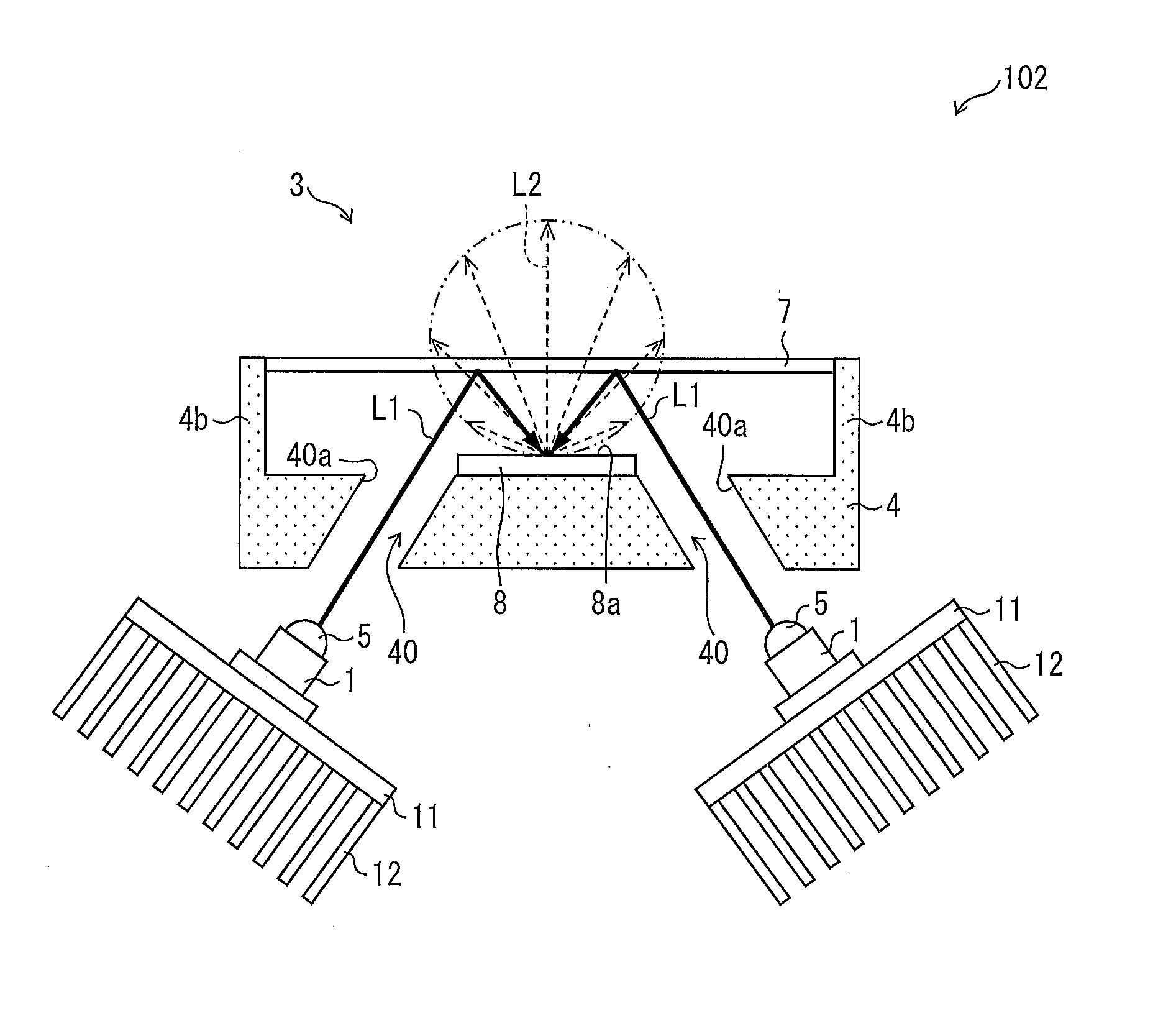
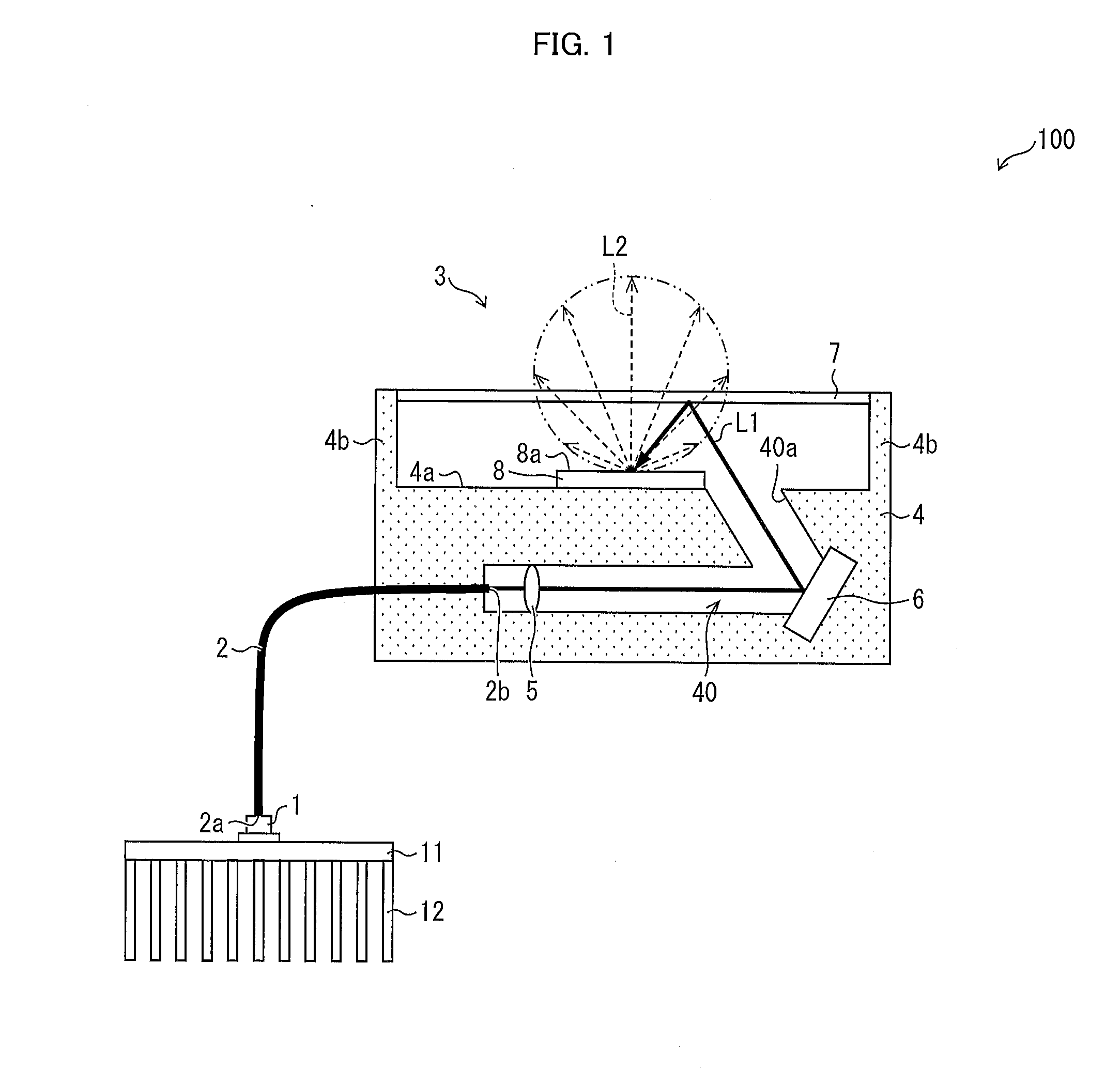
[0057]First, a light-emitting device 100 in accordance with Embodiment 1 will be described with reference to FIG. 1. The light-emitting device 100 emits, as illumination light, fluorescence (emission light) L2 that is generated by illuminating the fluorescent section 8, which contains particles of a fluorescent material, with the laser beam L1.

[0058]FIG. 1 is a cross-sectional view illustrating the configuration of the light-emitting device 100 in accordance with Embodiment 1. As illustrated in FIG. 1, the light-emitting device 100 includes a laser element (excitation light source) 1, an optical fiber (light guiding section) 2, and a light-emitting unit 3. The light-emitting device 100 is configured such that the laser element 1 a...

embodiment 2

[0165]The following will describe another embodiment of the present invention with reference to FIGS. 12 and 13. In Embodiment 2, a light-emitting device including a light intensity detecting section for detecting the intensity of a laser beam will be described.

[0166]For convenience of explanation, members of Embodiment 2 that are identical in function to their respective corresponding members described in Embodiment 1 are each assigned a common reference numeral, and are not described here.

[0167]First, a configuration of a light-emitting device 105 in accordance with Embodiment 2 will be described. The light-emitting device 105 emits, as illumination light, fluorescence (emission light) L2 that is generated by illuminating the fluorescent section 8, which contains particles of a fluorescent material, with a laser beam L1.

[0168]FIG. 12 is a cross-sectional view illustrating the configuration of the light-emitting device 105 in accordance with Embodiment 2. As illustrated in FIG. 12,...

embodiment 3

[0187]The following will describe still another embodiment of the present invention with reference to FIGS. 14 through 16. In Embodiment 3, a light-emitting device including a laser element located within a casing will be described.

[0188]For convenience of explanation, members of Embodiment 3 that are identical in function to their respective corresponding members described in Embodiments 1 and 2 are each assigned a common reference numeral, and are not described here.

[0189]First, a configuration of a light-emitting device 106 in accordance with Embodiment 3 will be described. The light-emitting device 106 emits, as illumination light, fluorescence (emission light) L2 that is generated by illuminating the fluorescent section 8, which contains particles of a fluorescent material, with a laser beam L1.

[0190]FIG. 14 is a cross-sectional view illustrating the configuration of the light-emitting device 106 in accordance with Embodiment 3. As illustrated in FIG. 14, the light-emitting dev...


PUM


Abstract

A light-emitting unit according to the present invention includes: a fluorescent section for emitting light upon irradiation with a laser beam; and a wavelength selection filter being provided so as to face the fluorescent section. The wavelength selection filter reflects the laser beam toward the fluorescent section and transmits fluorescence emitted from the fluorescent section.

Description

CROSS-REFERENCE TO RELATED APPLICATIONS[0001]This nonprovisional application claims priority under 35 U.S.C. §119 on Patent Application No. 2013-177316 filed in Japan on Aug. 28, 2013, Patent Application No. 2013-224748 filed in Japan on Oct. 29, 2013, and Patent Application No. 2014-048151 filed in Japan on Mar. 11, 2014, the entire contents of which are hereby incorporated by reference.FIELD OF THE INVENTION[0002]The present invention relates to a light-emitting unit, a light-emitting device, an illumination device, and a vehicle headlight each of which emits, as illumination light, light that is generated by irradiating a light emitting section with excitation light.BACKGROUND OF THE INVENTION[0003]In recent years, there has been suggested an illumination device which emits, as illumination light, fluorescence that is generated by irradiating a light emitting section containing particles of a fluorescent material with excitation light emitted by an excitation light source (i.e. s...

Claims


Application Information

Patent Timeline
Patent Type & Authority Applications(United States)
IPC IPC(8): F21S8/10
CPCF21S48/1145F21S48/1317F21Y2101/025F21Y2101/02F21S48/1225B60Q1/0023F21Y2115/30H01L2224/48091F21Y2115/10F21S41/285F21S41/675F21S41/16F21S41/365F21V9/30F21S41/176F21S41/337H01L2924/00014F21S43/14F21S43/30F21S43/255F21S43/26
Inventor TAKAHIRA, YOSHIYUKITAKAHASHI, KOJIMAEMURA, YOSUKESAKAUE, TOMOHIROTOYOTA, KENSEI
Owner SHARP FUKUYAMA LASER CO LTD
Why Eureka
Try Eureka